Motor-assisted variable geometry turbocharging system

Inactive Publication Date: 2000-03-14
HALIMI EDWARD MAYER
View PDF53 Cites 11 Cited by
  • Summary
  • Abstract
  • Description
  • Claims
  • Application Information

AI Technical Summary

Benefits of technology

In order to aid in the understanding of this invention, it can be stated in essentially summary form that it is directed to a motor-assisted variable geometry turbocharging system. The variable geometry is provided by the exhaust ga

Problems solved by technology

However, when operated over a broad range of engine speed and load, the compressor and turbine components are forced to function off their design points and consequently suffer losses in efficiency that affects engine performance adversely.
Conversely, if the turbocharger is matched to an engine's low speed range, the turbocharger will have a tendency to "overspeed" when the engine is operated at maximum speed and load.
The waste gate, however, allows the escape of exhaust gas energy, which could be better utilized by the turbocharger turbine and results in a substantial loss in system efficiency.
The various movable devices that have been employed in the turbocharger turbine have been complicated, expensive, and subject to questionable durability.
Consequently, they have met with limited commercial success.
However, this causes a movement of the compressor efficiency islands and choke area to lower flow and can result in lowering the compressor efficiency when the engine is operating at high speed and load.
Variable diffuser vanes is one type of variable geo

Method used


Image

  • Motor-assisted variable geometry turbocharging system
  • Motor-assisted variable geometry turbocharging system
  • Motor-assisted variable geometry turbocharging system

Examples


Embodiment Construction

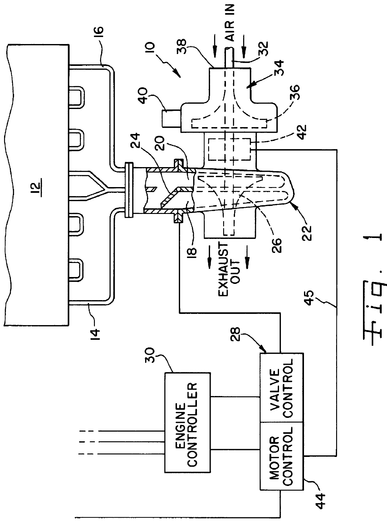
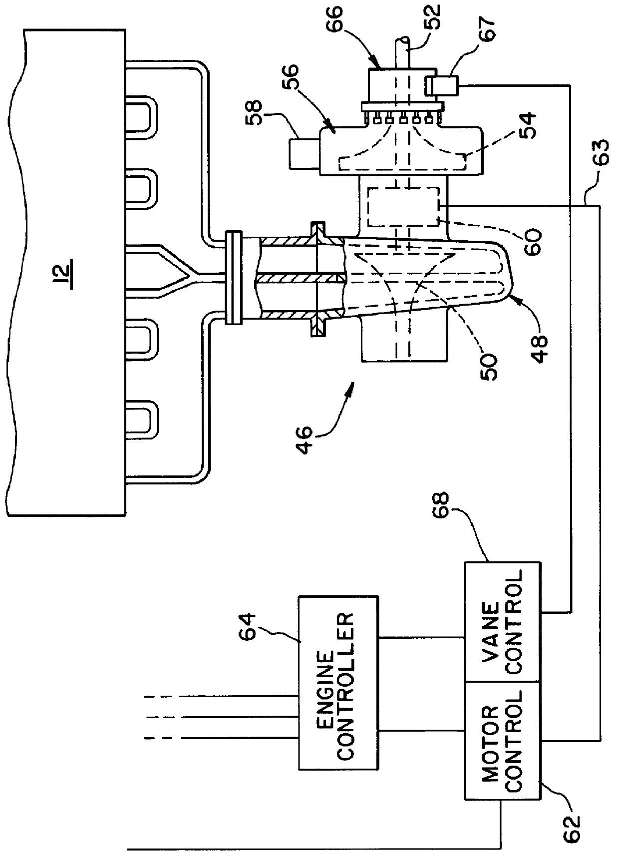
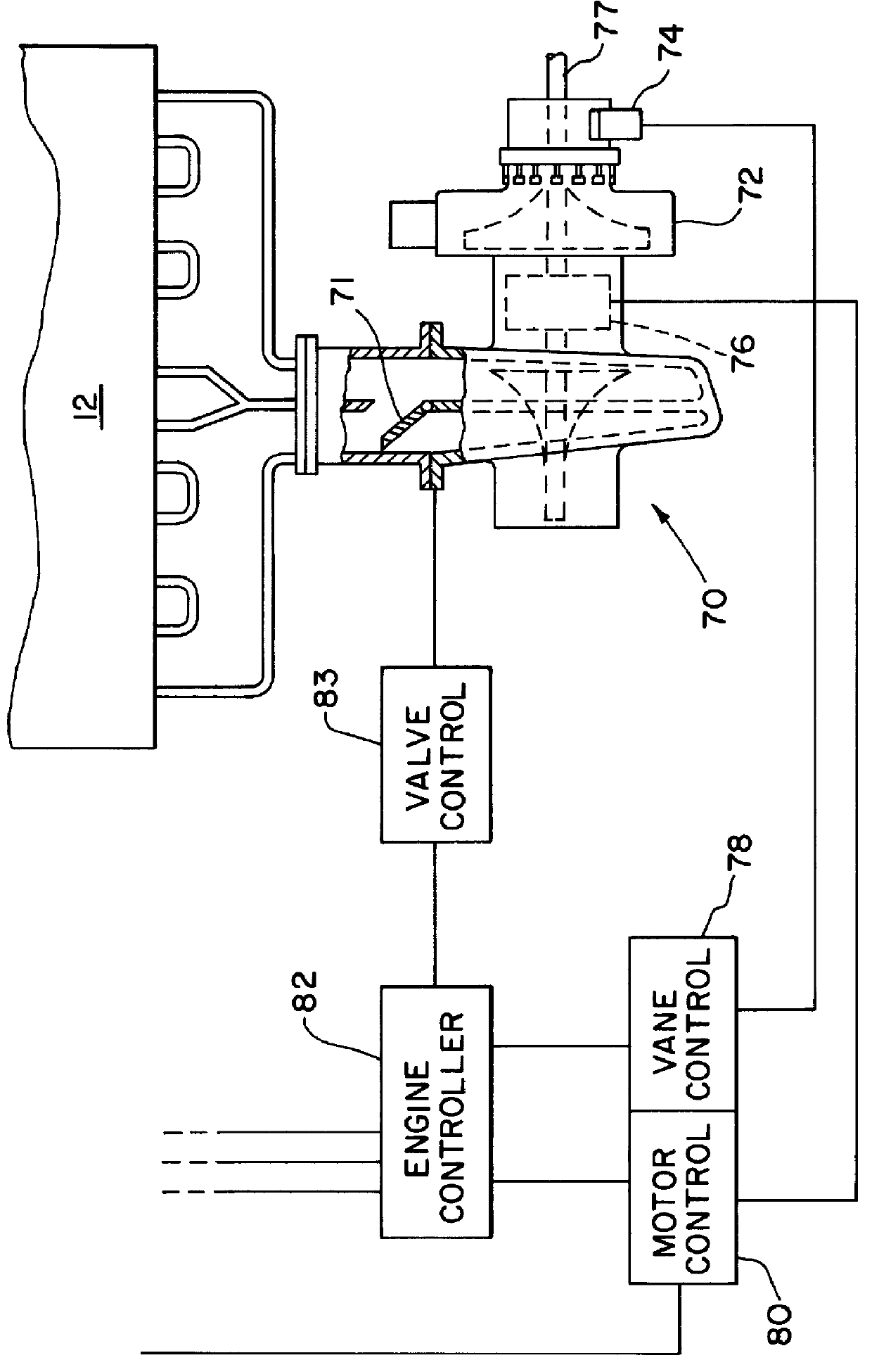
To improve engine and vehicle response to opening of the throttle, an external power source is needed to operate the turbocharger at higher speed at engine idle in order to provide increased boost levels in the engine intake system in preparation for quick acceleration. This external power source can be any convenient rotating power source, such as an electric motor, a hydraulic motor, a pneumatic motor, or the like, and particularly a motor which can have its power output controlled. A preferred example and the example given below of an external power source is an electric motor that engages the turbocharger rotor at engine idle and increases the idle speed of rotation of the rotating assembly.

Having higher boost pressure available at engine idle speed than the boost pressure the turbocharger can provide from exhaust gas energy alone, allows fuel to be injected into the engine cylinders sooner during acceleration and reduces smoke and emissions during the transient period. The engi...


PUM


Abstract

The motor-assisted variable geometry turbocharging system has a motor to add power to the turbocharging shaft, especially at low exhaust gas volume. Additionally, the turbocharger has control over compressor air inlet direction and/or control of exhaust gas to a two-volute expander. These are individually controlled directly or indirectly from an engine controller to enhance turbocharger performance. In a preferred embodiment, the motor is an electric motor, mounted directly on the turbocharger shaft intermediate the turbo expander and turbo compressor and within the main housing.

Description

FIELD OF THE INVENTIONThe present invention relates generally to variable geometry components used in turbochargers applied to internal combustion engines that operate over a broad range of speed and load.BACKGROUND OF THE INVENTIONFixed geometry turbochargers can be designed to operate efficiently at a particular engine load and speed. However, when operated over a broad range of engine speed and load, the compressor and turbine components are forced to function off their design points and consequently suffer losses in efficiency that affects engine performance adversely. If the turbocharger is matched to an engine at the engine's rated speed, it will run considerably off its maximum efficiency where the engine is "torqued down" to low engine operating speeds. Conversely, if the turbocharger is matched to an engine's low speed range, the turbocharger will have a tendency to "overspeed" when the engine is operated at maximum speed and load.To prevent overspeeding in turbochargers th...

Claims


Application Information

Patent Timeline
IPC IPC(8): F02B37/10F02B37/22F02B37/24F02B37/04F02B37/12F02B37/14F02B67/06F02B61/02F02B75/02F16H7/12
CPCF02B37/025F02B37/10F02B37/22F02B37/24F02B39/10F02B61/02Y02T10/144F02B2075/027Y02T10/12F02B37/14
Inventor HALIMI, EDWARD M.WOOLENWEBER, WILLIAM E.MALOOF, RALPH P.
Owner HALIMI EDWARD MAYER
Why Eureka
Try Eureka