Compression-encoded data decoding apparatus

a data decoding and compression technology, applied in the field of data decoding apparatuses, can solve the problems of reduced processing speed, increased standby time, and increased circuit scale of the entire apparatus, and achieve the effect of improving the performance of variable length decoding

Inactive Publication Date: 2005-01-20
KK TOSHIBA
View PDF13 Cites 2 Cited by
  • Summary
  • Abstract
  • Description
  • Claims
  • Application Information

AI Technical Summary

Benefits of technology

[0010] It is an object of the present invention to provide a data decoding apparatus for efficiently improving performance of variable length decoding.

Problems solved by technology

Thus, there is a problem that processing of the variable length decoder arranged at the front stage of the zero-run reconstruction device stops frequently every block, a standby time is increased until next processing has been enabled at the syntax interpreter or parameter decoder, and a processing speed is lowered.
As a result, the circuit scale of the entire apparatus is increased, and power consumption is increased.
As has been described above, in the conventional data decoding apparatus, the entire processing speed is slower due to the lowered processing efficiency of the variable length decoder.
Thus, there has been a problem that the circuit scale and power consumption are increased.

Method used


Image

  • Compression-encoded data decoding apparatus
  • Compression-encoded data decoding apparatus
  • Compression-encoded data decoding apparatus

Examples


first embodiment

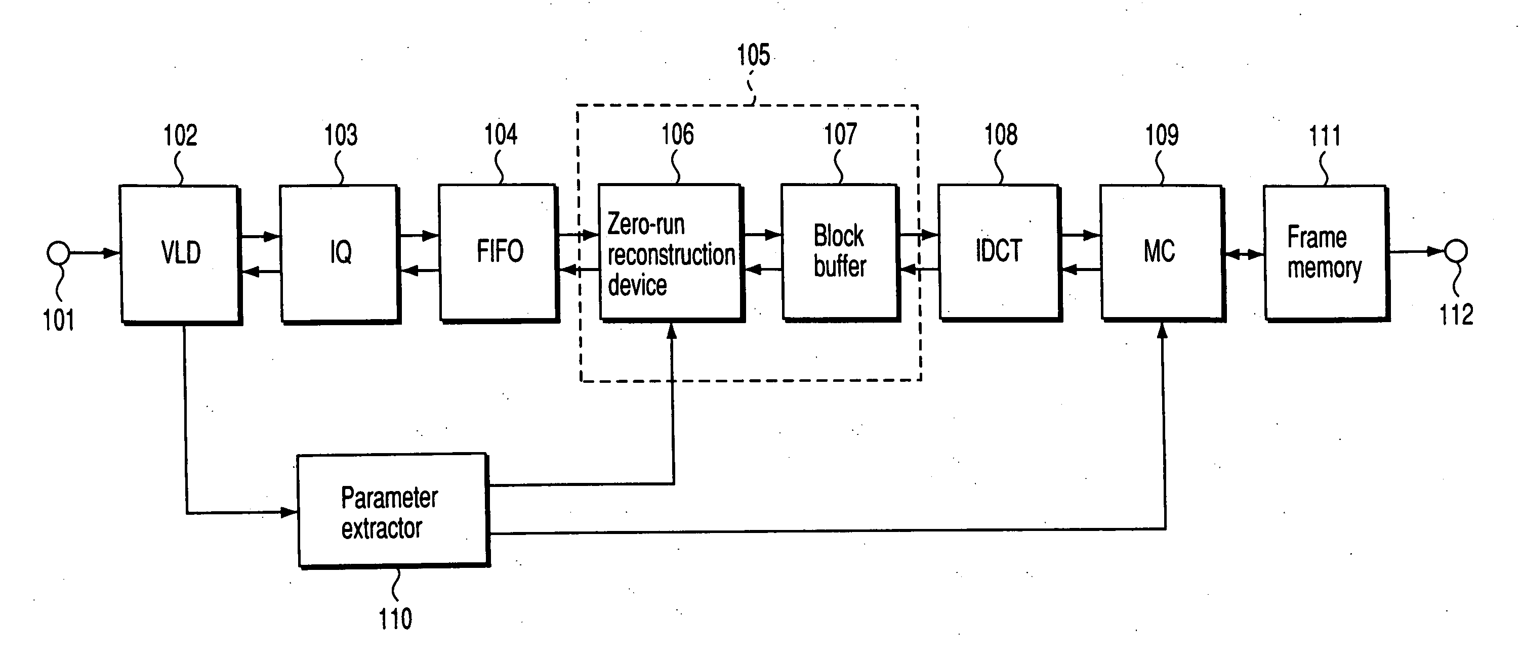
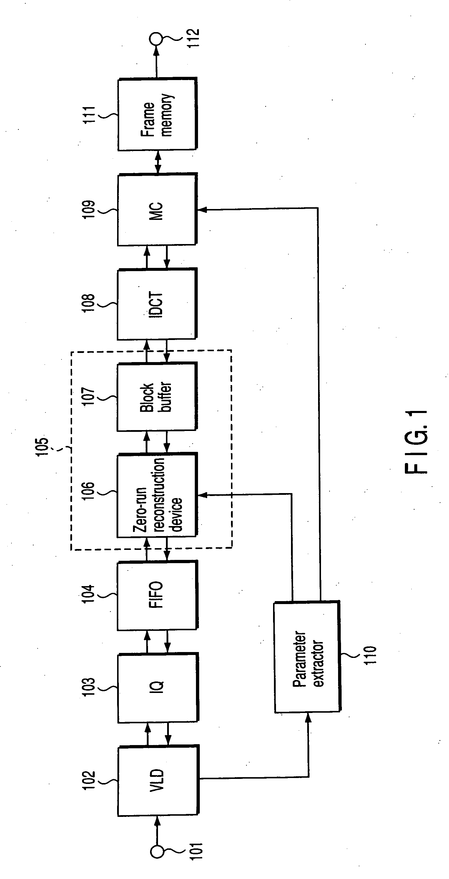
[0026]FIG. 1 shows a data decoding apparatus according to the present invention. Compression-encoded video data (encoded bit stream) obtained by compressing video data in accordance with an MPEG scheme, for example, by means of a video data encoding apparatus (not shown) inputs to an input terminal 101 via a transmission system or a storage medium. The compression-encoded video data is generated as follows by showing an example when the encoding scheme is the MPEG2 scheme.

[0027] First, a video signal to be encoded is divided into macro-blocks configured by a plurality of pixels (for example, 16 pixels×16 lines for luminance signal). Then, a video signal or a prediction error signal indicating an error between the video signal and a predictive signal is subjected to discrete cosine transformation (DCT) every block (configured by 8 pixels×8 lines). Next, coefficients (DCT coefficients) obtained by DCT are quantized in predetermined quantization step size, and further, the quantized co...

third embodiment

[0067]FIG. 5 is a view showing a data decoding apparatus according to the present invention. The present embodiment is directed to a configuration particularly suitable to decoding of the compression-encoded video data of a high definition digital television broadcast signal, wherein two pairs of decoding processors 120a and 120b and two pairs of parameter extractors 110a and 110b are provided.

[0068] The decoding processors 120a and 120b each comprise a variable length decoder 102, an inverse quantizer 103, a FIFO memory 104, and a zero-run reconstruction processor 105 (zero-run reconstruction device 106 and block buffer 107) shown in FIG. 1, and further, may comprise an intra-DC reproducer 113 shown in FIG. 4.

[0069] The decoding processors 120a and 120b receive two data streams corresponding to for example, two channels in units of slices or in units of pictures input, respectively, via input terminals 101a and 101b. In this time, DCT coefficients output from the block buffer 107 ...


PUM


Abstract

A decoding apparatus comprises a variable length decoder that decodes zero-run length and nonzero coefficient, an inverse quantizer that inverse-quantizes the nonzero coefficient, a zero-run reconstruction processor that reconstruct zero coefficients, a FIFO memory that store the zero-run length data and nonzero coefficients, an inverse discrete cosine transformer that subjects the coefficients to an inverse discrete cosine transformation, and a motion compensator that subjects the transformed result to a motion compensation.

Description

CROSS-REFERENCE TO RELATED APPLICATIONS [0001] This application is a continuation of and claims the benefit of priority under 35 USC §120 to application Ser. No. 09 / 942,607, filed Aug. 31, 2001 and is based upon and claims the benefit of priority under 35 USC §119 from Japanese Patent Application No. 2000-300433, filed Sep. 29, 2000, the entire contents of which are incorporated herein by reference.BACKGROUND OF THE INVENTION [0002] 1. Field of the Invention [0003] The present invention relates to a data decoding apparatus for decoding compression-encoded video data with a low delay and at a high speed, the compression-encoded video data being obtained by compression-encoding a video image in accordance a video encoding scheme as represented by an MPEG scheme employing Discrete Cosine Transformation (DCT). [0004] 2. Description of the Related Art [0005] Conventionally, it has been well known that an MPEG video decoder is employed as a data decoding apparatus for decoding, with a com...

Claims


Application Information

Patent Timeline
Patent Type & Authority Applications(United States)
IPC IPC(8): H03M7/40H04N19/60H04N19/423H04N19/44H04N19/625H04N19/91H04N19/93
CPCH04N19/61H04N19/42H04N19/44H04N19/91
Inventor UETANI, YOSHIHARU
Owner KK TOSHIBA
Why Eureka
Try Eureka