Variable geometry turbine

Active Publication Date: 2013-11-07
MITSUBISHI HEAVY IND LTD
View PDF0 Cites 1 Cited by
  • Summary
  • Abstract
  • Description
  • Claims
  • Application Information

AI Technical Summary

Benefits of technology

The invention provides a design for a variable geometry turbine that improves efficiency at low flow rates and enhances performance. This is achieved by adding projections on one of the surfaces of the nozzle vanes that cover the spaces between the leading and trailing edges of the nozzle vanes when they are at a closed position. This prevents a decrease in efficiency when the flow rate is low and improves the performance of the turbine.

Problems solved by technology

These gaps serve as fluid leakage paths and, thus, decrease the efficiency of the variable geometry radial turbine.

Method used


Image

  • Variable geometry turbine
  • Variable geometry turbine
  • Variable geometry turbine

Examples


first embodiment

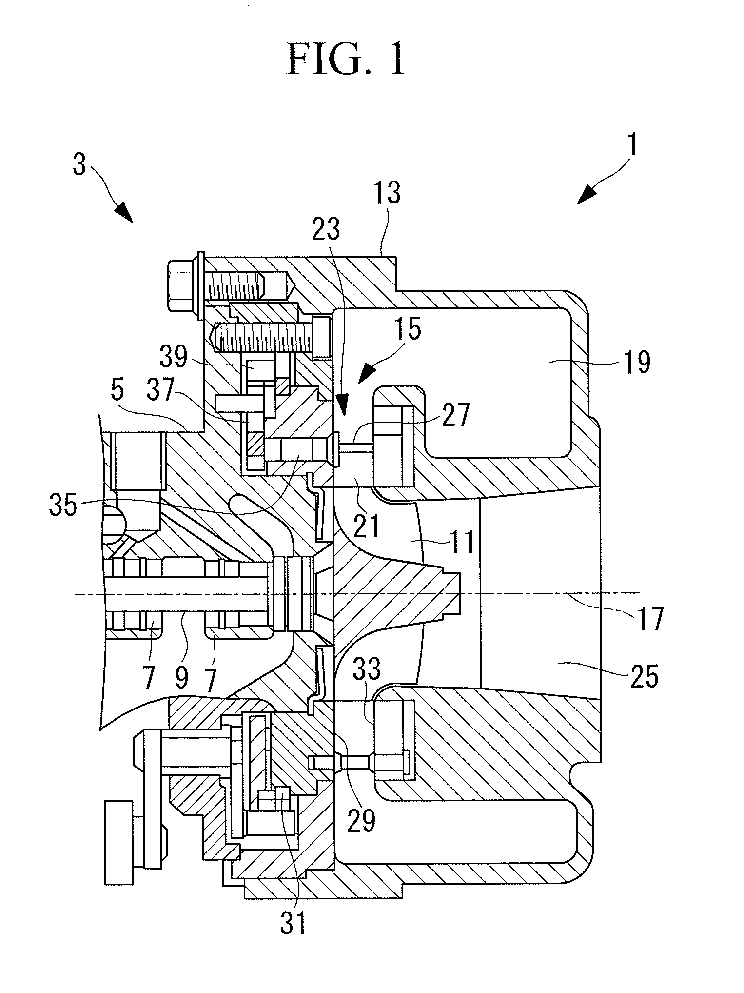
[0047]A variable geometry turbocharger having a variable geometry radial turbine 1 according to a first embodiment of the present invention will be described with reference to FIGS. 1 to 4.

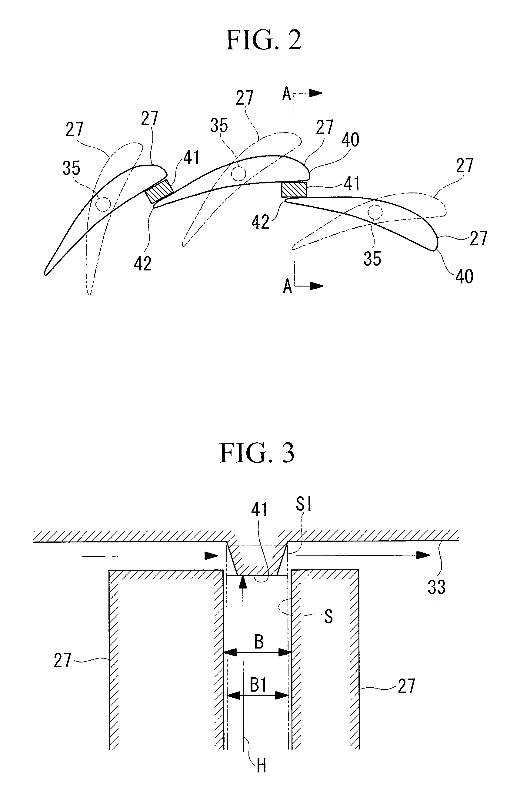
[0048]FIG. 1 is a partial sectional view showing, in outline, the configuration of a variable geometry radial turbine side of a variable geometry exhaust turbocharger according to a first embodiment of the present invention. FIG. 2 is a plan view showing some of the nozzle vanes in FIG. 1. FIG. 3 is a cross-sectional view taken along line A-A in FIG. 2. FIG. 4 is a cross-sectional view showing a nozzle mount portion.

[0049]A variable geometry turbocharger 3 includes the variable geometry radial turbine 1 and a compressor (not shown).

[0050]The variable geometry radial turbine 1 and the compressor are joined via a bearing housing 5. A turbine rotor 9 supported in a rotatable manner by a bearing 7 passes through the bearing housing 5.

[0051]The compressor includes a compressor wheel (not shown) attache...

second embodiment

[0077]Next, a variable geometry turbocharger having a variable geometry radial turbine 1 according to a second embodiment of the present invention will be described with reference to FIGS. 5 to 7.

[0078]Because this embodiment differs from the first embodiment in the configuration of the nozzle plate 33, the differences will be mainly described in this section, and overlapping descriptions of commonalities with the above-described first embodiment will be omitted.

[0079]Note that components in common with those of the first embodiment will be denoted by the same reference numerals.

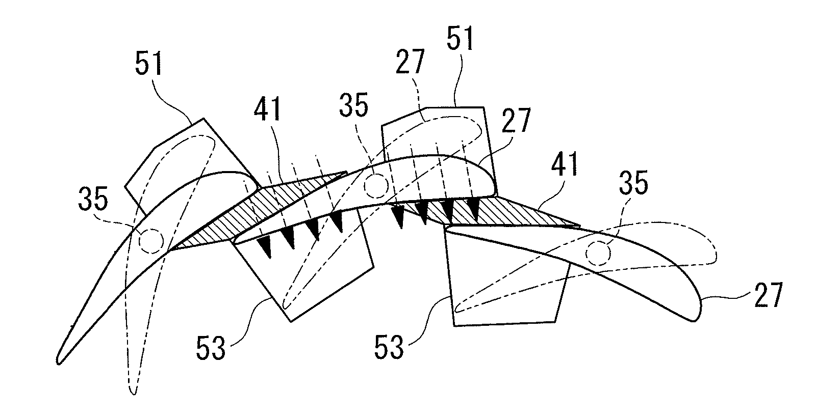
[0080]FIG. 5 is a plan view showing some of the nozzle vanes of the variable geometry radial turbine 1 according to this embodiment. FIG. 6 is a cross-sectional view taken along line B-B in FIG. 5. FIG. 7 is a cross-sectional view taken along line C-C in FIG. 5.

[0081]In this embodiment, the nozzle plate 33 has tapered outer-circumferential surfaces 51 formed on the outer circumferential side of the plate pro...

third embodiment

[0090]Next, a variable geometry turbocharger having a variable geometry radial turbine 1 according to a third embodiment of the present invention will be described with reference to FIGS. 8 to 10.

[0091]Because this embodiment differs from the first embodiment in the configuration of the nozzle plate 33, the differences will be mainly described in this section, and overlapping descriptions of commonalities with the above-described first embodiment will be omitted.

[0092]Note that components in common with those of the first embodiment will be denoted by the same reference numerals.

[0093]FIG. 8 is a plan view showing some of the nozzle vanes of the variable geometry radial turbine 1 according to this embodiment. FIG. 9 is a cross-sectional view taken along line D-D in FIG. 8. FIG. 10 is a cross-sectional view taken along line E-E in FIG. 8.

[0094]In this embodiment, the nozzle plate 33 has tapered inner-circumferential surfaces 53 formed on the inner circumferential side of the plate pr...


PUM


Abstract

A variable geometry turbine includes a fluid space formed by a nozzle mount and a nozzle plate; and a plurality of nozzle vanes arranged in the fluid space at certain intervals in the circumferential direction so as to partition the fluid space. The nozzle vanes are supported by shafts on the nozzle mount, in such a manner as to be capable of turning. The flow rate of the discharged fluid can be adjusted by opening or closing the cross-sectional area of a flow path formed by the adjacent nozzle vanes. The nozzle plate is provided with plate projections protruding toward the nozzle vanes further than, at least, end surfaces of the nozzle vanes, so as to cover the spaces between leading edges of the nozzle vanes and trailing edges of the nozzle vanes adjacent thereto, when the nozzle vanes are at a closed position.

Description

TECHNICAL FIELD [0001]The present invention relates to variable geometry turbines.BACKGROUND ART [0002]A radial turbine has a configuration in which a plurality of centrifugal blades are fixed to a hub secured to a rotating shaft, and in which working fluid, i.e., air or gas, flowing from the radially outer circumferential side toward the inner side through a flow path between a nozzle mount and a nozzle plate, which have a ring-like shape and are provided substantially parallel to each other, acts on the centrifugal blades to rotate the hub and is discharged substantially in an axial direction.[0003]In the flow path between the circular plates, a plurality of nozzle vanes for accelerating the working fluid are arranged with gaps therebetween in the circumferential direction.[0004]A variable geometry radial turbine has a configuration in which the nozzle vanes are supported by shafts on the nozzle mount and turn on the shafts to open or close throat spaces formed by adjacent nozzle ...

Claims


Application Information

Patent Timeline
IPC IPC(8): F01D17/16
CPCF01D17/165F02B37/24F02C6/12F05D2220/40
Inventor YOKOYAMA, TAKAOSUZUKI, HIROSHIEBISU, MOTOKIYOSHIDA, TOYOTAKA
Owner MITSUBISHI HEAVY IND LTD
Why Eureka
Try Eureka