

Descaling wheel for cement bin
A cement silo and wheel body technology, which is applied in the field of cement silo descaling wheels, can solve the problems of difficult removal of cement scale, damage to the cement silo body, and heavy workload of descaling, achieving high descaling efficiency and long service life , Improve the effect of descaling effect
Inactive Publication Date: 2015-02-11
HUANGSHI ZHIYUN ELECTROMECHANICAL TECH INST
View PDF0 Cites 0 Cited by
- Summary
- Abstract
- Description
- Claims
- Application Information
AI Technical Summary
Problems solved by technology
[0002] Most existing tools for removing cement scale use hammers or steel rods with pointed heads. Using this kind of scale removal tool has the following problems: the workload of scale removal is large, the scale removal is difficult to clean, and the scale removal efficiency is low. Careless operation will damage the cement silo and is unsafe
Method used
View moreImage
Smart ImageViewing Examples

Examples
Embodiment Construction
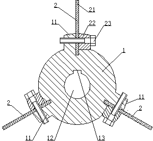
[0007] see figure 1 , the present invention comprises a wheel body 1 and three descaling assemblies 2 uniformly distributed in the circumferential direction, the wheel body 1 is provided with three protrusions 11 uniformly distributed in the circumferential direction, and an inner hole 12 and Keyway 13, described each descaling assembly 2 comprises spring steel sheet 21, pressing block 22 and screw 23, one end of described spring steel sheet 21 is inserted in the groove of wheel body 1, and described spring steel sheet 21 adopts pressing Block 22 and screw 23 are compressed on the wheel body 1.
Login to View More PUM
 Abstract
The invention discloses a descaling wheel for a cement bin. The descaling wheel is characterized by comprising a wheel body (1) and three descaling assemblies (2) which are uniformly distributed in the circumferential direction; three bumps (11) which are uniformly distributed in the circumferential direction are arranged on the wheel body (1); an inner hole (12) and a key groove (13) are formed in the central position of the wheel body (1); each descaling assembly (2) comprises a spring steel sheet (21), a pressing block (22) and a screw (23); one end of each spring steel sheet (21) is inserted into a groove of the wheel body (1); each spring steel sheet (21) is compressed on the wheel body (1) by adopting the corresponding pressing block (22) and the corresponding screw (23). The descaling wheel disclosed by the invention has the advantages of high descaling efficiency, convenience for dismounting and mounting, safety and reliability, and long service life.
Description
technical field [0001] The invention relates to cement equipment, in particular to a descaling wheel for a cement silo. Background technique [0002] Most existing tools for removing cement scale use hammers or steel rods with pointed heads. Using this kind of scale removal tool has the following problems: the workload of scale removal is large, the scale removal is difficult to clean, and the scale removal efficiency is low. Careless operation will damage the cement silo and is unsafe. Contents of the invention [0003] The object of the present invention is to provide a cement silo descaling wheel with high descaling efficiency, convenient assembly and disassembly, safety and reliability, and long service life. [0004] In order to achieve the above object, the present invention includes a wheel body and three uniformly distributed descaling components in the circumferential direction, the wheel body is provided with three uniformly distributed protrusions in the circum...
Claims
Login to View More Application Information
Patent Timeline
 IPC IPC(8): B65D88/64
CPCB65D88/68
Inventor黄凌志
OwnerHUANGSHI ZHIYUN ELECTROMECHANICAL TECH INST