
vehicle control system

A vehicle control system and control circuit technology, applied to vehicle components, transmission control, brakes, etc., can solve the problems of inability to ensure the safety of the wire control system and the inability to quickly stop the mechanical operation of the wire control system

Active Publication Date: 2017-07-04
DENSO CORP
View PDF8 Cites 0 Cited by
  • Summary
  • Abstract
  • Description
  • Claims
  • Application Information

AI Technical Summary

Problems solved by technology

As a result, when the remote control system is abnormal, the mechanical operation of the remote control system cannot be stopped quickly
As a result, it may not be possible to ensure the safety of the wire control system when an abnormality occurs

Method used


Image

  • vehicle control system
  • vehicle control system
  • vehicle control system

Examples


no. 1 example

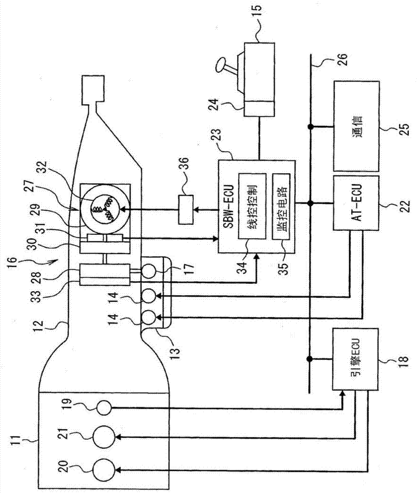
[0015] will refer to Figure 1 to Figure 5 The first embodiment will be described. First, refer to figure 1 A schematic configuration of an automatic transmission control system for a vehicle will be described.

[0016] An input shaft of the automatic transmission 12 is coupled to an output shaft (crankshaft) of the engine 11 . The automatic transmission 12 has a transmission gear mechanism (not shown), a friction engagement device (not shown), a hydraulic control unit 13 and the like. The friction engagement device switches the combination (speed ratio) of the power transmission gears among the plurality of wheels constituting the transmission gear mechanism. The hydraulic control unit 13 hydraulically switches the operating state of the friction engagement device. The hydraulic control unit 13 has a hydraulic control valve 14 and a manual valve 17 . The hydraulic pressure control valve 14 controls hydraulic pressure supplied to frictional engagement members such as clut...

no. 2 example

[0085] will refer to Figure 6 The second embodiment will be described. Substantially the same parts as those in the first embodiment are designated with the same reference numerals to simplify description, and only different parts will be described below.

[0086] According to the second embodiment, as Figure 6 As shown in , a control circuit other than the drive-by-wire control circuit 34 of the SBW-ECU 23 is configured to have the function of the drive determination section 39 . In particular, the shift control circuit 44 of the AT-ECU 22 has the function of the drive determination unit 39 . The shift control circuit 44 of the AT-ECU 22 determines permission and prohibition of driving the electric motor 29 by the drive determination unit 39 . When it is determined that the driving of the electric motor 29 is prohibited, that is, when the driving of the electric motor 29 is not permitted, the driving of the electric motor 29 is prohibited by the first drive prohibiting m...


PUM


Abstract

When the diagnostic unit (40) of the wire-by-wire control circuit (34) determines that the wire-by-wire shift system is abnormal or the monitoring circuit (35) determines that the wire-by-wire control circuit (34) is abnormal, the SBW‑ECU will pass the drive prohibition device (36 ) to disable the drive of the electric motor (29) by shutting off the power supply to said motor. In this case, when the motor (29) is driven to rotate under the condition that the shift-by-wire system is determined to be abnormal, by performing power supply phase fixing processing (thus, the power supply phase of the motor (29) is fixed without being switched) to prevent the motor (29) from rotating. Then, said inhibiting means (36) inhibits the driving of said motor (29) by stopping the power supply to said motor (29).

Description

technical field [0001] The present invention relates to a vehicle control system having a drive-by-wire system that controls a synchronous motor supplied as a drive power source for a device mounted on a vehicle through a drive-by-wire control circuit. Background technique [0002] In recent years, in order to meet the requirements of saving space, simplifying assembly work, improving control performance, etc., more and more mechanical drive systems have been replaced by drive-by-wire systems driven by electric motors. [0003] In the control-by-wire system disclosed in JP-A-2006-336691 (US 2006 / 0271260 A1), a monitoring control circuit such as an engine control circuit is provided independently of a control-by-wire control system that controls A motor that is supplied as a driving power source. The monitor control circuit monitors the drive-by-wire control system based on predetermined monitor information. When the monitoring control circuit detects an abnormality of the ...

Claims


Application Information

Patent Timeline
Patent Type & Authority Patents(China)
IPC IPC(8): F16H61/18F16H61/12
CPCF16H61/18B60T1/062B60T13/586F16D63/002H02P6/24
Inventor 木村纯山田纯筱岛政明
Owner DENSO CORP
Learn More