Inverted tooth gravel conveying pipe

A technology of conveying pipes and inverted teeth, which is applied in the field of conveying pipes, can solve problems such as backflow, and achieve high work efficiency

Inactive Publication Date: 2015-02-11
常州能建电力辅机有限公司
View PDF0 Cites 2 Cited by
  • Summary
  • Abstract
  • Description
  • Claims
  • Application Information

AI Technical Summary

Problems solved by technology

[0003] In order to overcome the lack of backflow of debris in existing delivery pipes, the present invention provides an inverted-toothed gravel delivery pipe

Method used


Image

  • Inverted tooth gravel conveying pipe

Examples


Embodiment Construction

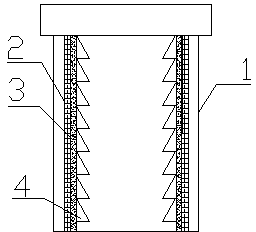
[0011] like figure 1 It is a schematic diagram of the structure of the present invention. The inverted-toothed gravel conveying pipe includes a pipe steel matrix 1, a metal alloy transition layer 2 and superhard material particles 3. The inner wall of the pipeline steel matrix 1 is provided with a metal alloy transition layer 2 and superhard material particles. 3. The metal barb 4 is fixed on the pipeline steel base 1, the tip of the metal barb 4 faces the direction of the delivery pipe outlet, and the metal barb 4 is a high manganese steel barb.

[0012] The pipeline steel matrix 1 is covered with metal barbs 4, and the metal barbs 4 are made of high manganese steel, which can ensure their wear resistance, and the tip orientation of the metal barbs 4 can prevent debris from flowing in from the opposite direction. The conveying pipe can prevent the debris flowing in the pipe from flowing backwards, thus making the dredging work more efficient.


PUM


Abstract

The invention relates to a conveying pipe, in particular to an inverted tooth gravel conveying pipe. The conveying pipe comprises a pipeline steel substrate, a metal alloy transition layer and superhard material particles, wherein the metal alloy transition layer and the superhard material particles are arranged on an internal wall of the pipeline steel substrate; metal inverted teeth are fixed on the pipeline steel substrate; tooth tips of the metal inverted teeth face an outlet of the conveying pipe; the metal inverted teeth are high manganese steel inverted teeth; the conveying pipe can prevent sundries flowing in the pipe from backflow, so that the working efficiency of dredging is higher.

Description

technical field [0001] The invention relates to a conveying pipe, in particular to an inverted tooth type gravel conveying pipe. Background technique [0002] Existing river dredging requires the use of conveying pipes to suck out sludge, sand and other debris, and the metal alloy coating in the pipeline is the main treatment for the wear resistance of the conveying pipe, but the debris in the pipeline may Backflow will occur due to external pressure, thereby reducing the efficiency of its sewage discharge. Contents of the invention [0003] In order to overcome the deficiency that the debris in the existing conveying pipes will flow back, the present invention provides an inverted-tooth sandstone conveying pipe. [0004] The technical solution adopted by the present invention to solve the technical problem is: the inverted-tooth sandstone conveying pipe, including the pipe steel matrix, the metal alloy transition layer and the superhard material particles, and the metal ...

Claims


Application Information

Patent Timeline
Patent Type & Authority Applications(China)
IPC IPC(8): F16L9/14
CPCF16L9/14
Inventor 陈国平
Owner 常州能建电力辅机有限公司
Why Eureka
Try Eureka