Chamber for heat treatment equipment and heat treatment equipment

A heat treatment device and chamber technology, which is applied in the manufacture of electrical components, circuits, semiconductors/solid-state devices, etc., can solve the problems of labor and time, and achieve the effect of reducing labor and time

Active Publication Date: 2015-02-11
KOYO THERMO SYST CO LTD
View PDF6 Cites 1 Cited by
  • Summary
  • Abstract
  • Description
  • Claims
  • Application Information

AI Technical Summary

Problems solved by technology

Such welding operations are labor-intensive and time-consuming

Method used


Image

  • Chamber for heat treatment equipment and heat treatment equipment
  • Chamber for heat treatment equipment and heat treatment equipment
  • Chamber for heat treatment equipment and heat treatment equipment

Examples


Embodiment Construction

[0038] Hereinafter, a mode for implementing the present invention will be described with reference to the drawings. In addition, the present invention can be widely applied to heat treatment devices that heat treatment objects to be processed.

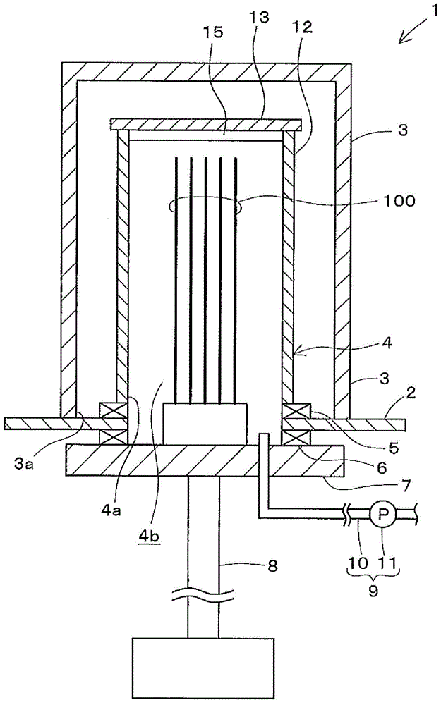
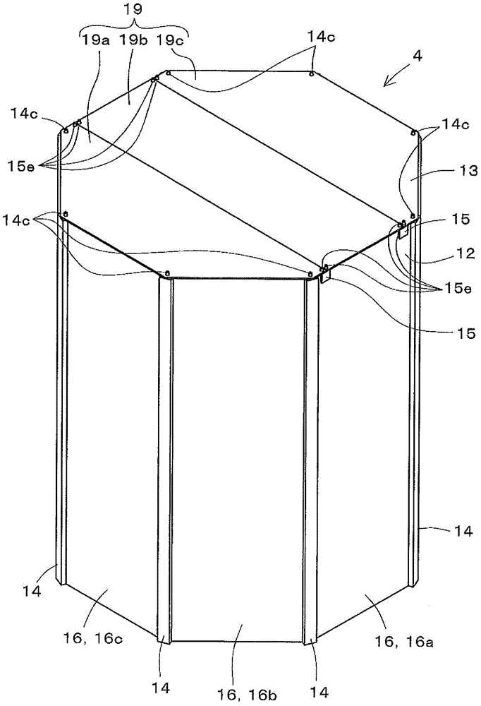
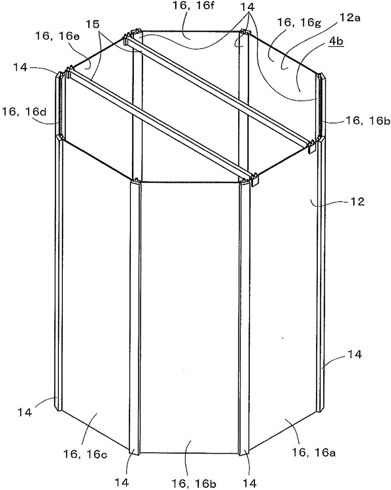
[0039] figure 1 This is a cross-sectional view of the heat treatment apparatus 1 according to the embodiment of the present invention, and shows a state of the heat treatment apparatus 1 viewed from the side. figure 2 It is a perspective view of the chamber 4 of the heat treatment apparatus 1. image 3 It is an exploded perspective view of the chamber 4. Figure 4 It is a cross-sectional view of the chamber 4, and shows a state in which the chamber 4 is viewed from above.

[0040] Reference figure 1 The heat treatment apparatus 1 is configured to be able to perform heat treatment on the surface of the object 100 to be processed. More specifically, the heat treatment apparatus 1 is configured to be able to perform heat treatment on the surf...


PUM


Abstract

The invention provides a chamber for heat treatment equipment and the heat treatment equipment. Even if the chamber for the heat treatment equipment is large-scale, the labour and time spending on the manufacture of the chamber can be further reduced. The chamber (4) for the heat treatment equipment (1) comprises a cannular sidewall (12) used for surrounding an object to be treated and an end wall (13) which closes an opening part (12b) at one side of the sidewall (12). The chamber (4) is formed in a way that a plurality of parts (the sidewall (12), the end wall (13), a first connecting part (14) and a second connecting part (15)) are mechanically combined, and the major component of the parts is silicon oxide.

Description

Technical field [0001] The present invention relates to a chamber of a heat treatment device and a heat treatment device for processing an object to be processed in a heated environment. Background technique [0002] A heat treatment apparatus for heat treatment of a processed substrate such as a glass substrate is known (for example, refer to Patent Document 1). As an example of the heat treatment apparatus, the heat treatment apparatus described in Patent Document 1 has a heat treatment container. The heat treatment container is a quartz tube. [0003] Prior technical literature [0004] Patent Document 1: Japanese Patent Application Publication No. 2010-177653 (paragraph 0017) [0005] In recent years, with the increase in the size of processed substrates, the size of the quartz tube has also tended to increase. Among them, it is difficult to replace the quartz tube with a metal tube due to strength reasons. Therefore, a larger size quartz tube is sought. However, it is diffic...

Claims


Application Information

Patent Timeline
IPC IPC(8): H01L21/67
CPCH01L21/67098
Inventor 笠次克尚西村圭介浦崎义彦森川清彦中西裕也
Owner KOYO THERMO SYST CO LTD
Why Eureka
Try Eureka