
Automatic waste collecting and lifting mechanism

A waste collection and elevator technology, applied in conveyors, loading/unloading, containers, etc., can solve the problems of high input cost, long construction period, inconvenient movement, etc. Effect

Inactive Publication Date: 2017-02-15
东风(十堰)汽车部件有限公司
View PDF5 Cites 1 Cited by
  • Summary
  • Abstract
  • Description
  • Claims
  • Application Information

AI Technical Summary

Problems solved by technology

[0003] The invention provides an automatic waste collection and lifting mechanism, which solves the problems of high investment cost, long construction period and inconvenient movement in the existing waste collection system

Method used


Image

  • Automatic waste collecting and lifting mechanism
  • Automatic waste collecting and lifting mechanism
  • Automatic waste collecting and lifting mechanism

Examples


Embodiment Construction

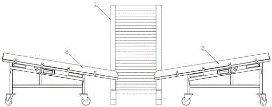
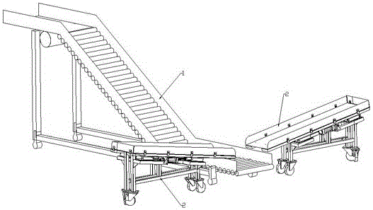
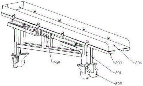
[0010] like figure 1 , figure 2 and image 3 As shown, an automatic waste collection and lifting mechanism includes a waste conveying hoist 1 and a waste collection shaking machine 2 that are independent of each other. The two waste collecting shaking machines 2 are respectively located on the left and right sides of the waste conveying elevator 1. The discharge end of the shaker 2 and the feed end 1 of the waste conveying hoist are set up and down correspondingly; the structure of the waste collection shaker 2 is: including a frame 201, a universal wheel 202, a slideway 203, a hopper 204 and a cylinder 205, the universal wheel 202 is fixed on the bottom of the frame 201, the universal wheel 202 is convenient for the frame to move, the slideway 203 provided with an inclination is fixed on the top of the frame 201, the hopper 204 is arranged in the slideway 203, the hopper 204 and the slideway Road 203 is slidingly connected, cylinder 205 is fixed on the frame, and the pisto...


PUM


Abstract

An automatic waste collecting and lifting mechanism comprises a waste conveying and lifting machine and waste collecting and shaking machines which are independent from one another. The discharge ends of the waste collecting shaking machines are arranged corresponding to the feed end of the waste conveying and lifting machine in the vertical direction. Each waste collecting and shaking machine structurally comprises a rack, universal wheels, a slide way, a hopper and an air cylinder, wherein the universal wheels are fixed to the lower portion of the rack, the slide way which is obliquely arranged is fixed to the top of the rack, the hopper is arranged in the slide way, the air cylinder is fixed to the rack, a piston rod in the air cylinder is hinged to the bottom of the hopper, and the hopper reciprocates through the air cylinder in the direction of the slide way. The mechanism is arranged on the ground, can be moved through the universal wheels, is good in flexibility, low in weight, small in investment and short in period and basically does not influence existing production modes and plans.

Description

technical field [0001] The invention belongs to the field of waste transfer of stamping parts, in particular to an automatic waste collection and lifting mechanism. Background technique [0002] At present, most of the waste collection systems around the stamping equipment adopt the underground channel mode, which has high investment costs and a long construction period; but for most stamping enterprises at present, the transformation is difficult and difficult to realize. Contents of the invention [0003] The invention provides an automatic waste collection and lifting mechanism, which solves the problems of high investment cost, long construction period and inconvenient movement in the existing waste collection system. [0004] In order to solve the above-mentioned technical problems, the technical solution of the present invention is: an automatic waste material collection and lifting mechanism, which includes a waste material conveying hoist and a waste material colle...

Claims


Application Information

Patent Timeline
IPC IPC(8): B65G65/42B65D88/54
CPCB65G65/425B65D88/54B65G2201/04
Inventor 杨进斌陈文超刘广刘畅
Owner 东风(十堰)汽车部件有限公司
Learn More