
High frequency component and filter component

一种元器件、高频的技术,应用在高频元器件领域,能够解决增多线圈卷绕数、层叠体大型化等问题,达到削减层数、优秀高频特性的效果

Active Publication Date: 2015-02-11
MURATA MFG CO LTD
View PDF6 Cites 10 Cited by
  • Summary
  • Abstract
  • Description
  • Claims
  • Application Information

AI Technical Summary

Problems solved by technology

However, increasing the opening of the coil or increasing the number of windings of the coil will increase the size of the laminated body

Method used


Image

  • High frequency component and filter component
  • High frequency component and filter component
  • High frequency component and filter component

Examples


Embodiment Construction

[0038] Next, the high-frequency component according to Embodiment 1 will be described. The high-frequency components shown here constitute a high-pass filter having a cutoff band on the low-frequency side of the passband.

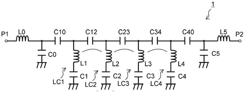
[0039] figure 1 It is an equivalent circuit diagram of the high-frequency component 1 according to the first embodiment. The high-frequency component 1 is composed of input and output ports P1, P2, capacitors C0, C1, C2, C3, C4, C5, C10, C12, C23, C34, C40, and inductors L0, L1, L2, L3, L4, and L5. high-pass filter.

[0040] In the high-frequency component 1, the inductor L1 and the capacitor C1 constitute a series resonant circuit LC1. Likewise, the inductor L2 and the capacitor C2 constitute a series resonant circuit LC2. Inductor L3 and capacitor C3 form a series resonant circuit LC3. Inductor L4 and capacitor C4 form a series resonant circuit LC4. A capacitor C12 is connected between the resonance circuits LC1 and LC2. Likewise, a capacitor C23 i...


PUM


Abstract

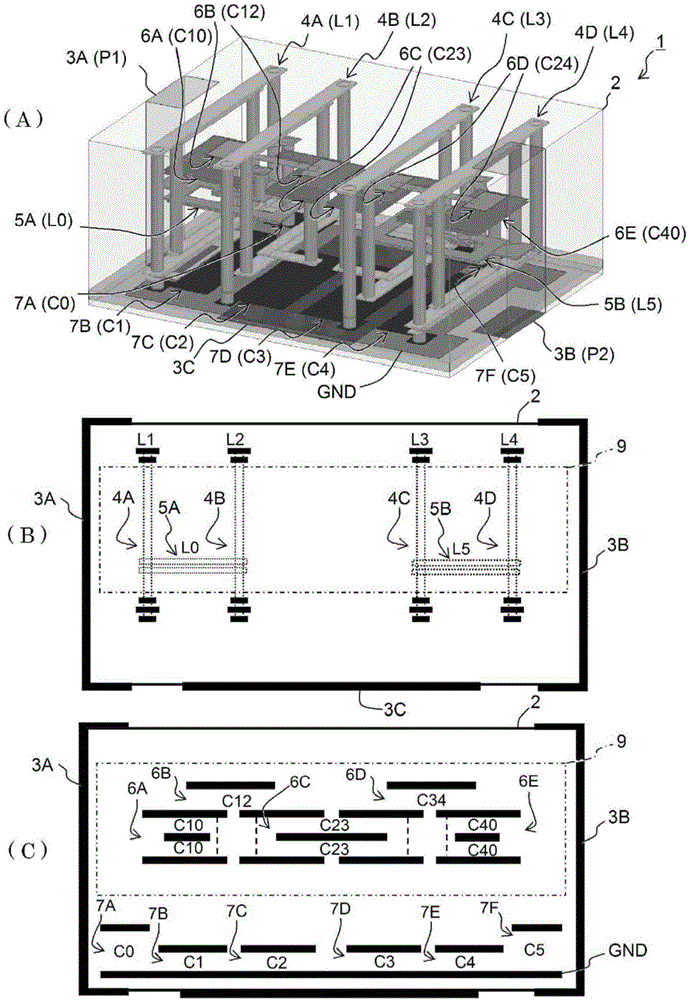
A high frequency component includes a multilayer body (2) including a plurality of insulating layers stacked in a stacking direction, linear conductors extending along the insulating layers, interlayer connection conductors extending through at least one of the insulating layers, and planar conductors expanding along the insulating layers. The high frequency component further includes transverse coils (4A, 4B, 4C, 4D) and internal capacitors (6A, 6B, 6C, 6D). Each of the transverse coils includes the linear conductors and the interlayer connection conductors spirally wound in a plane in a plurality of turns around a winding axis extending in a direction substantially perpendicular to the stacking direction. Each of the internal capacitors includes the planar conductors being opposite each other such that at least one of the insulating layers is disposed therebetween, the internal capacitor being arranged within a coil opening of the transverse coil when seen along the winding axis of the transverse coil.

Description

technical field [0001] The present invention relates to a high-frequency component comprising an LC circuit on a laminate. Background technique [0002] A component obtained by forming an LC circuit on a laminate is used as a high-frequency component. Since such high-frequency components with LC circuits are required to be able to handle various frequencies and realize filter characteristics with steep attenuation poles, it is necessary to appropriately set the number of stages of the resonant circuit constituting the LC circuit and the circuit constants of the LC circuit. [0003] When the inductor constituting the LC circuit is formed of a coil-shaped conductor pattern, the inductance can be increased by increasing the coil opening or increasing the number of windings of the coil. However, increasing the opening of the coil or increasing the number of windings of the coil results in an increase in the size of the laminated body. Therefore, in order to increase the number...

Claims


Application Information

Patent Timeline
Patent Type & Authority Applications(China)
IPC IPC(8): H03H1/02
CPCH03H7/0161H01F2017/0026H03H7/1758H01F17/0013H03H7/1766H03H7/1775H03H7/0115H03H2001/0085H03H7/09
Inventor 渡边邦广
Owner MURATA MFG CO LTD
Learn More