

Red-green-blue polymeric interference film
a polymer and interference film technology, applied in the field of optical films, can solve the problems of only observing the color shifting effect provided by these materials, unable to meet backlit applications, and loss of color saturation, and achieves the effects of high degree of color uniformity, less abruptness, and high degree of physical and optical caliper uniformity
- Summary
- Abstract
- Description
- Claims
- Application Information
AI Technical Summary
Benefits of technology
Problems solved by technology
Method used
Image

Examples
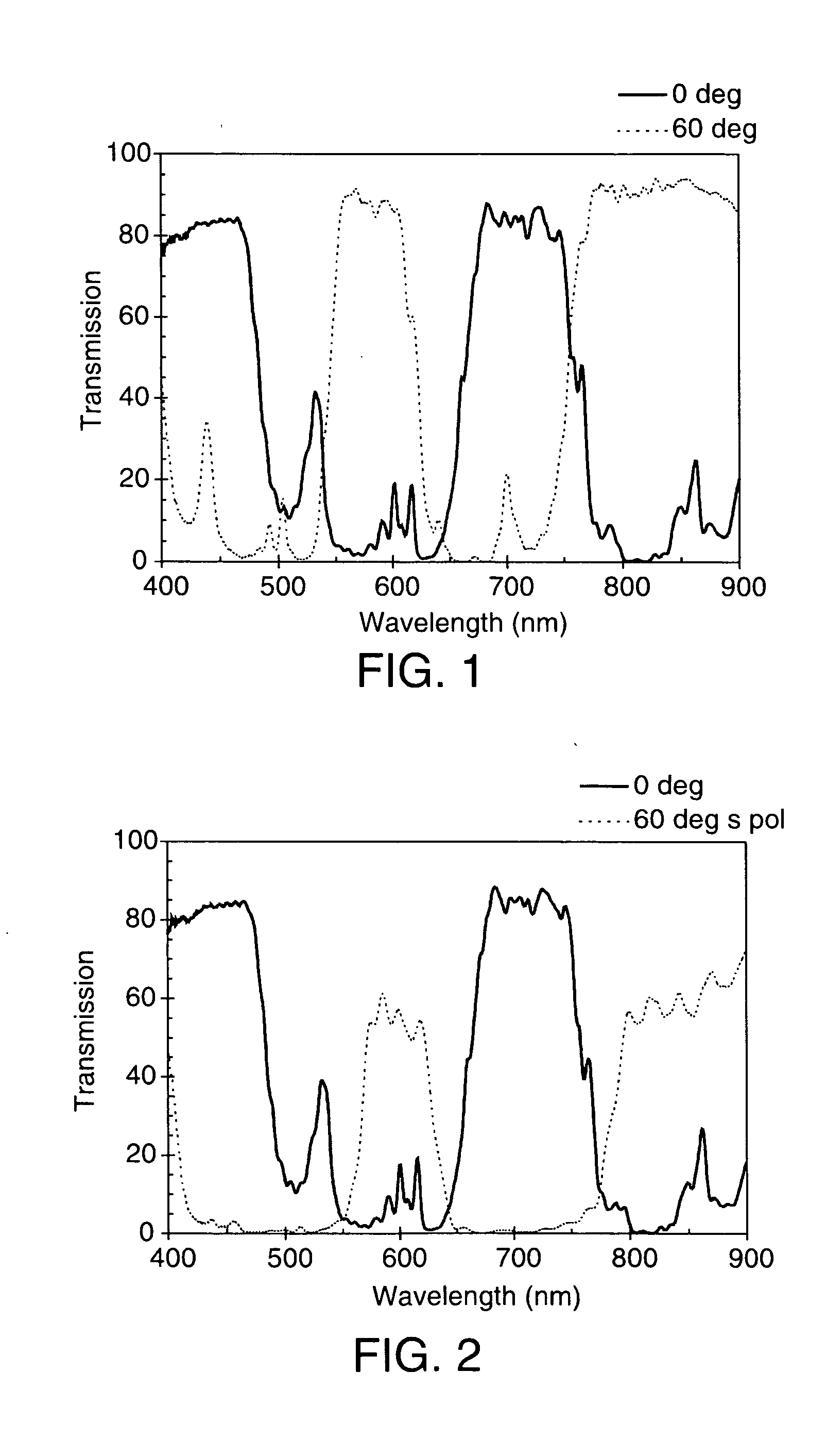
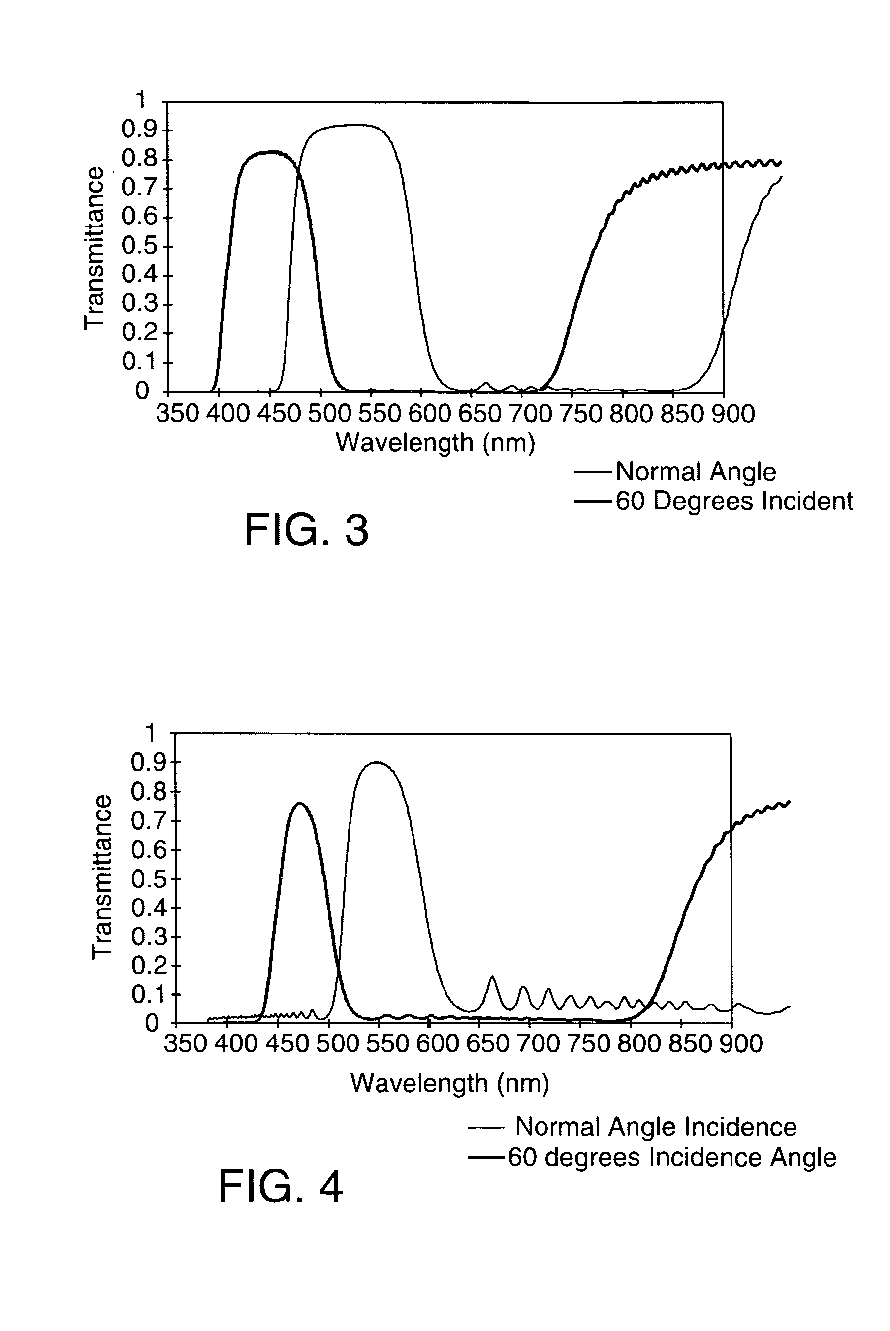
example b1-1
A film was made in accordance with EXAMPLE E1-2, but with about a 30% slower casting wheel speed. The transmission spectrum at normal incidence and at 60° for p-polarized light is shown in FIG. 1. The transmission spectrum at normal incidence and at 60° for s-polarized light is shown in FIG. 2.
Using the definitions given below for bandedge and slope, the following values were measured for this example: the stop band near 600 nm at normal incidence has a bandwidth of 103 nm (543 to 646 nm) and an average transmission of 5.5% within that stopband. The blue bandedge has a slope of 0.66% per nm, while the red edge has a slope of 2.1% per nm. The passband at 700 nm at normal incidence has a bandwidth of 100 nm and a maximum transmission of 85%. The slopes of the passband bandedges are: 2.3 percent per nm on the blue side, and 1.9 percent per nm on the red side. Note that the shape of the entire spectral curve is substantially the same at a 60° angle of incidence as compared to normal ...
examples b5-1
AND B5-2
The transmission color for an 80-layer optical stack consisting of alternating layers of materials A and B, with in-plane refractive index values Na=1.75 and Nb=1.50 and designed to provide a saturated “blue” transmission spectrum (given a uniform white illumination source) at normal angle, was calculated as a function of angle from 0 degrees to 80 degrees. Transmission color was calculated using both the CIE x-y chromaticity coordinates and the La*b* color space. For each color system, color saturation increases as the color coordinate values move away from the illumination source color values: (0,0) for La*b*, and (0.333,0.333) for the x-y system.
For each color coordinate system, a comparison in color values versus viewing angle was made for a multilayer system where the refractive indices along the z-axis have values nza=1.75, nzb=1.50 (EXAMPLE B5-1, the isotropic, z-index mismatched case) and nza=1.50, nzb=1.50 (EXAMPLE B5-2, the z-index matched, birefringent case). A...
example b7-1
The transmission spectra for s and p-polarized light of a 417 layer coextruded PET / Ecdel film are shown in FIG. 9. Both spectra were taken at 60 degrees angle of incidence in air, which is equivalent to about 35 degrees in glass having an index of 1.52 such as e.g., BK-7 glass., This multilayer film was made as described in EXAMPLE E1-2. As described in that example, the process used to make this multilayer sample utilized an asymmetric two times layer multiplier which doubles the number of layers produced in the feedblock. The multiplier was designed so that the two sets of layers are tuned to reflect separate wavelength bands, centered at wavelengths separated by the multiplier ratio. However, the multipliers do not produce the exact same multiplication ratio at all points across the meltstream. In particular, there is often a considerable change in ratio near one or both edges of the film. For convenience, the sample of this example was taken near one edge of the film described ...
PUM
| Property | Measurement | Unit |
|---|---|---|
| optical thickness | aaaaa | aaaaa |
| optical thickness | aaaaa | aaaaa |
| optical thickness | aaaaa | aaaaa |
Abstract
Description
Claims
Application Information