Elastic coupler having locking-unlocking function

A combination and elastic technology, which is applied in the field of elastic combination with unlocking function, can solve the problems of slotted or cross-groove tool wear, expansion of multiple combinations, combined objects cannot be rotated in opposite directions, etc., to prevent The effect of wear and tear

Active Publication Date: 2015-02-11
株式会社乐博特思
View PDF6 Cites 8 Cited by
  • Summary
  • Abstract
  • Description
  • Claims
  • Application Information

AI Technical Summary

Problems solved by technology

Therefore, there is a disadvantage that when the bolt is repeatedly used, the slot or the cross groove is worn by the tool.
However, in the case of bolts and nuts, the combination between the combined objects is always a fixed combination, and the combined state is maintained so that the combined objects cannot rotate in opposite directions.
In addition, in order to connect bolts and nuts, at least one side of each combined body needs to be opened. Therefore, it is impossible to repeatedly combine three or more multi-layered combined bodies in units of 2 to extend or expand the multiple joints.

Method used


Image

  • Elastic coupler having locking-unlocking function
  • Elastic coupler having locking-unlocking function
  • Elastic coupler having locking-unlocking function

Examples


Embodiment Construction

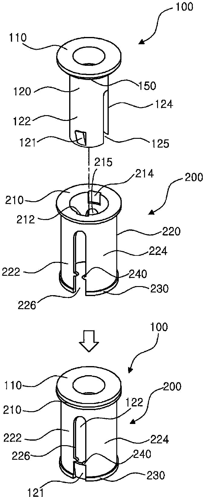
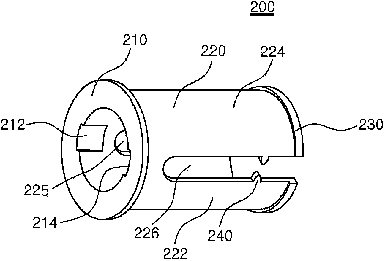
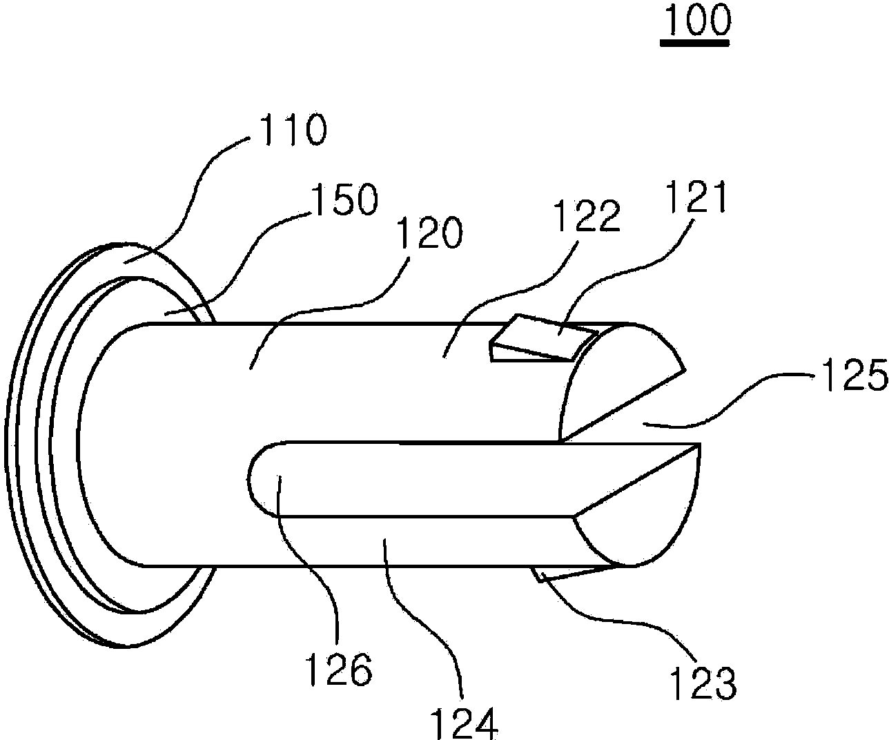
[0029] Refer to the attached Figure 1 to Figure 5 Preferred embodiments of the present invention are described in more detail. The embodiments of the present invention can be modified in various forms, and the scope of the present invention is not limited to the embodiments described below. This embodiment is provided to explain the present invention in more detail to those skilled in the technical field of the present invention. Therefore, the shape of each element in the drawings may be exaggerated in order to emphasize clearer illustration.

[0030] figure 1 is a schematic illustration of an isolated cross-sectional view of an elastic combination according to an embodiment of the present invention; figure 2 to represent figure 1 The cross-sectional view of the hollow sleeve shown in ; image 3 to represent figure 1 A cross-sectional view of the retaining pin shown in .

[0031] like Figure 1 to Figure 3 As shown, the elastic combination has a hollow sleeve 200 an...


PUM


Abstract

An elastic coupler, according to one embodiment of the present invention, comprises: a hollow socket having an upper holding protrusion and a lower holding protrusion which are inserted into a first insertion hole and a second insertion hole which are respectively formed in a first object to be coupled and a second object to be coupled so as to couple the first object to be coupled and second object to be coupled and respectively protrude from an outer peripheral surface so as to be disposed on the upper end portion and the lower end portion of the hollow socket, and two or more guide slots which are formed on the outer peripheral surface from the lower end in a direction parallel to the direction of insertion; support pins which are inserted into the hollow socket so as to limit the movement of the upper holding protrusion and the lower holding protrusion towards the inside of the hollow socket; and fixing pins having two or more guide protrusions which protrude from the outer peripheral surfaces of the support pins and respectively move along the guide slots.

Description

technical field [0001] The present invention relates to an elastic combination, and in more detail relates to an elastic combination with unlocking function. Background technique [0002] A typical example of a conventional coupling body for coupling two or more types of components to be coupled is bolts and nuts, and the bolts and nuts firmly couple the components to be coupled with coupling screws. However, since the bolt is formed with a slot or a cross groove, it is necessary to insert another tool such as a screwdriver into the slot or the cross groove to couple the bolt to the nut. Therefore, there is a disadvantage that the slotted groove or the cross groove is worn by the tool when the bolt is repeatedly used. [0003] In particular, when bolts and nuts made of low-strength materials such as plastics are used, the screw threads are worn by the bonding force of the bolts and nuts, resulting in the generation of plastic powder. [0004] Moreover, when the combined bo...

Claims


Application Information

Patent Timeline
IPC IPC(8): A63H33/04A63H33/10A63H33/12
CPCA63H33/12A63H33/04
Inventor 金炳洙李玎镐
Owner 株式会社乐博特思
Why Eureka
Try Eureka