Drilling tool and drilling device

A drilling tool and chamfering device technology, which is applied in metal processing and other directions, can solve the problems that drilling and pressing R angle cannot be carried out at the same time, the drilling device is not universal, and the drilling quality is poor, so as to avoid stress wear and Effects of material corrosion, cost reduction, and process reduction

Pending Publication Date: 2020-08-25
YANFENG PLASTIC OMNIUM AUTOMOTIVE EXTERIOR SYST
View PDF0 Cites 0 Cited by
  • Summary
  • Abstract
  • Description
  • Claims
  • Application Information

AI Technical Summary

Problems solved by technology

[0007] The invention provides a drilling tool and a drilling device to solve the technical problems in the prior art that the drilling device is not universal, the drilling quality is poor, and drilling and pressing the R angle cannot be performed simultaneously.

Method used


Image

  • Drilling tool and drilling device
  • Drilling tool and drilling device
  • Drilling tool and drilling device

Examples


Embodiment 1

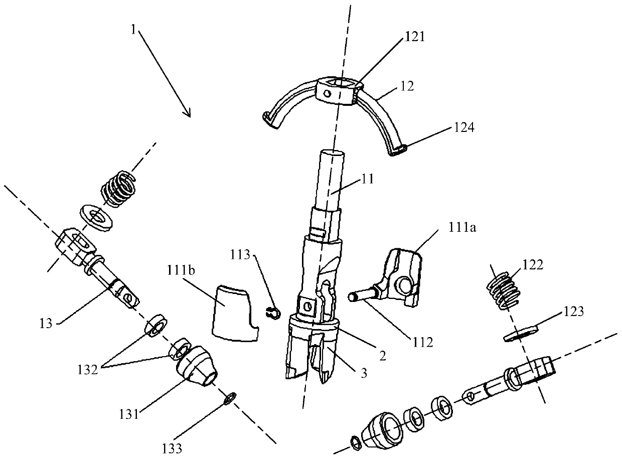
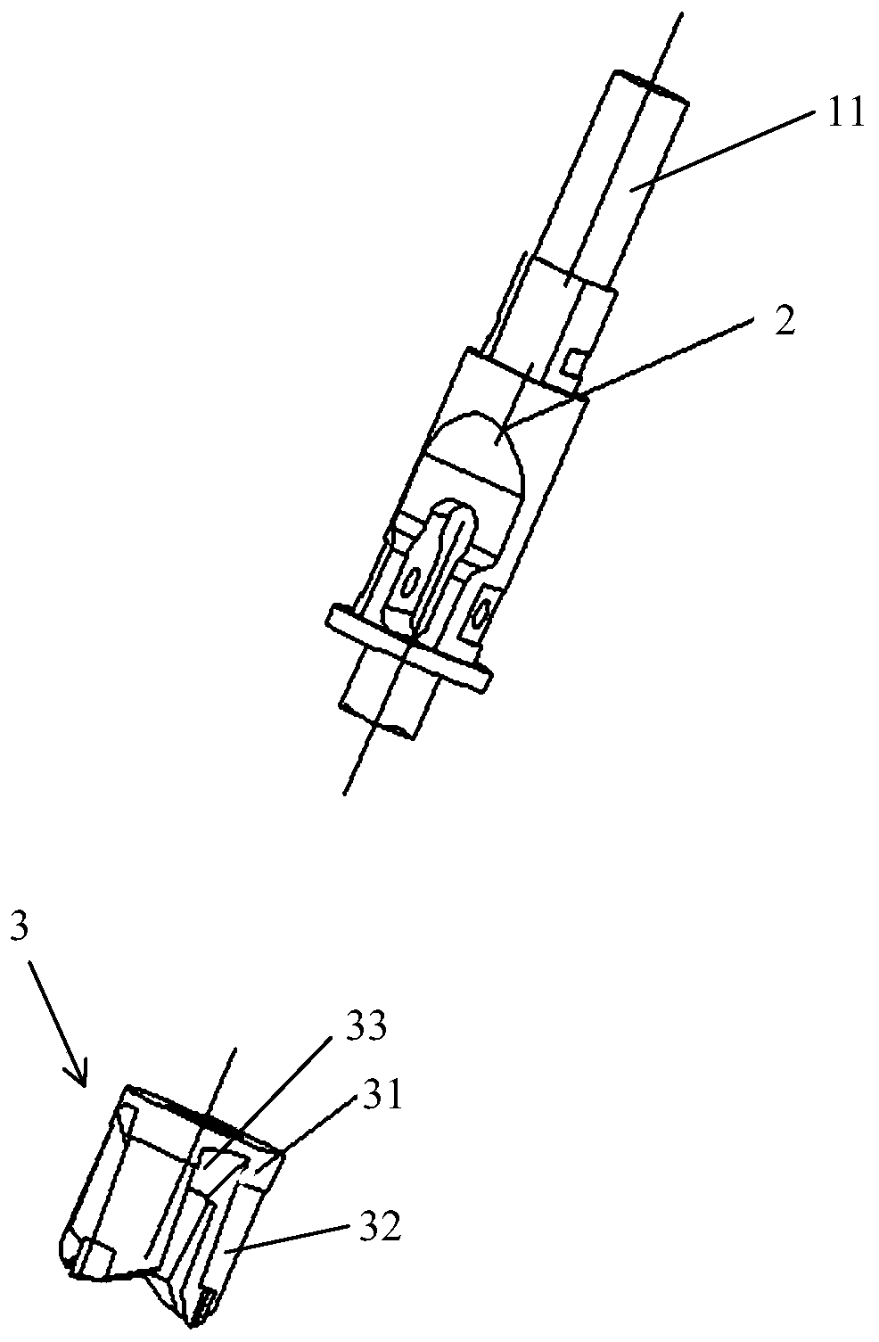
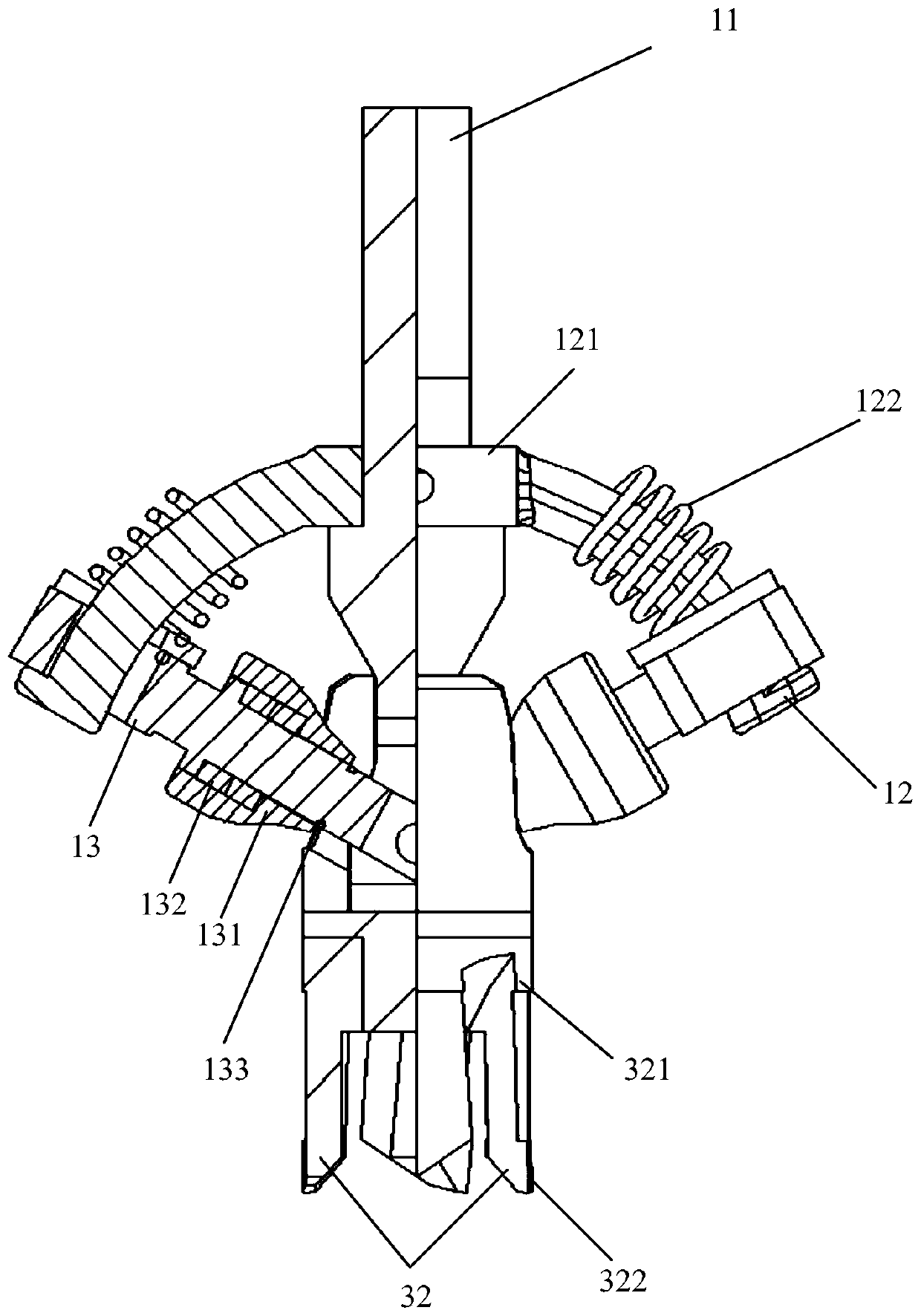
[0052] Such as figure 1 and 2 As shown, the embodiment of the present invention provides a drilling tool, including a chamfering device 1, a handle 2 and a cutter body 3, wherein the chamfering device 1 is used to press the R angle of the product (ie bumper), including a transmission Positioning main shaft 11, guide shaft 12 and roller 13, guide shaft 12 is the arc-shaped structural part that has through hole in the middle part, the upper end of transmission positioning main shaft 11 passes through the middle part through hole of guide shaft 12, and roller 13 is two pairs, two One end of each is pivotally connected to the lower end of the transmission positioning main shaft 11, while the other ends of the two rollers 13 are respectively slidably connected to the arc sections of the guide shaft 12 that are separated on both sides of the through hole. The lower end of the transmission positioning main shaft 11 refers to It is the end away from the through hole of the guide shaf...

Embodiment 2

[0072] This embodiment provides a drilling device, which includes a driving member and the drilling tool as described in Embodiment 1. The driving shaft of the driving member is connected with the transmission and positioning spindle 11 of the drilling tool, and is used to drive the transmission and positioning spindle 11 to rotate. And vertical movement, so as to complete the work of drilling and pressing R angle.

[0073] Specifically, the driving member may be a motor, and the output shaft of the motor is connected with the transmission positioning main shaft 11 to drive its rotation and vertical movement.

[0074] In a feasible implementation, the driving part is a robot, and the mechanical arm of the robot is connected with the transmission positioning spindle 11 to drive its rotation and vertical movement. Meanwhile, the robot can also automatically control the drilling tool, thereby realizing automatic production.

[0075] The drilling device provided in the embodiment ...


PUM


Abstract

The invention relates to a drilling tool and a drilling device. The drilling tool comprises a tool body, a tool handle connected with the tool body and a chamfering device, wherein the chamfering device comprises a guide shaft, a transmission positioning main shaft and pin rollers; the guide shaft is an arc-shaped piece with a through hole formed in the middle; the upper end of the transmission positioning main shaft penetrates through the through hole; the lower end of the transmission positioning main shaft is connected with one ends of the two symmetrically-distributed pin rollers in a pivoted mode; and the other ends of the two pin rollers are connected with the arc-shaped sections, positioned on the two sides of the through hole, of the guide shaft in a sliding mode correspondingly. According to the drilling tool and the drilling device, the chamfering device, the tool handle and the tool body are organically combined together, drilling and R angle pressing are synchronously conducted, drilling and R angle pressing can be completed only through one device, the production cost is greatly reduced, and the production efficiency is improved.

Description

technical field [0001] The invention relates to the field of automobile exterior decoration, and more particularly relates to a drilling tool and a drilling device. Background technique [0002] At present, in the passenger car industry, the surface hole types (radar hole, cleaning hole, assembly hole) processing process of large-scale exterior plastic parts (such as front and rear bumpers) are all: after injection molding and coating, special drilling devices are used to complete. The forming of the hole, and then use the R-angle pressing equipment to process the R-angle of the hole. However, there are many problems in this prior art, mainly in the following aspects: [0003] 1. The drilling device cannot be used universally. At present, the various types of holes on the surface of automotive exterior products are different in shape, so special drilling machines are used to process different products separately, and the equipment cannot be used universally. However, with...

Claims


Application Information

Patent Timeline
IPC IPC(8): B26F1/16B26D5/08
CPCB26D5/086B26F1/16
Inventor 金启扬李育弟
Owner YANFENG PLASTIC OMNIUM AUTOMOTIVE EXTERIOR SYST
Why Eureka
Try Eureka