Snapping roller for corn harvester

A technology of corn harvester and ear picking roller, which is applied to harvesters, agricultural machinery and implements, applications, etc., can solve the problems of broken rollers in the traction part, poor feeding effect, easy damage to the rollers, etc., and achieve long service life and excellent structure Reasonable, easy-to-use effect

Inactive Publication Date: 2015-02-18
潍坊昌荣机械有限公司
7 Cites 2 Cited by

AI-Extracted Technical Summary

Problems solved by technology

[0002] The ear picking roller of the traditional corn harvester has a complex structure, and some problems were found during use. 1. The feeding effect is poor. 1. The straw is easy to be blocked between the rollers, causing the shutdown; 2. The roller is ...

Method used

Adopt the fringe picking roller in the present embodiment when in use, roller rack 4 ' is not provided with roller tooth 4 on the position near tower head 1 ', so smooth roller rack 4 ' plays guiding role, makes in actual The feeding effect is good during use, which avoids the blockage of the stalk a...

Abstract

The invention discloses a snapping roller for a corn harvester. The snapping roller comprises a roller body sleeved by a roller housing, wherein a snapping device used for snapping corn ears is arranged outside the roller housing; the snapping device comprises a roller rack which is spirally fixed and wound on the outer surface of the roller housing; the roller rack extends to be close to the end part of the roller housing and consists of a guiding part and a connecting part on which a plurality of roller teeth are uniformly arranged; the guiding part is not provided with roller teeth.

Application Domain

Harvesters

Technology Topic

EngineeringMechanical engineering

Image

  • Snapping roller for corn harvester
  • Snapping roller for corn harvester

Examples

  • Experimental program(1)

Example Embodiment

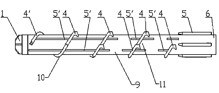
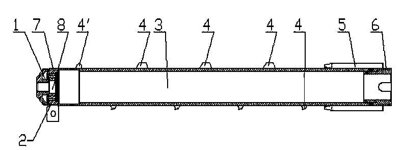
[0022] Examples, as attached figure 1 And figure 2 As shown, a corn harvester ear picking roller includes a roller 3, the roller 3 is sheathed with a roller shell 9, and the roller shell 9 is provided with a picking device for picking ears.
[0023] The picking device includes a roller rack 4', which is spirally wound around the outer surface of the roller housing 9, and the roller rack 4'extends to a position close to the end of the roller housing 9, The roller rack 4 ′ is composed of a guide part 10 and a connecting part 11. The connecting part 11 is provided with a plurality of roller teeth 4. The roller teeth 4 are uniformly arranged on the connecting part 11, and the guide part 10 is not provided with roller teeth 4.
[0024] The guide portion 10 occupies 1/3 of the length of the roller rack 4'; the end of the roller 3 close to the guide portion 10 is connected with a tower head 1, the roller 3 has a sleeve portion 7', and the tower head 1'is sleeved in the sleeve Outside the connecting portion 7, a bearing 8 is provided between the sleeve connecting portion 7 and the roller housing 9, and the bearing 8 is connected to the bearing seat 2.
[0025] A number of auxiliary broaches 5'are fixed on the outer wall of the roller shell 9, and the auxiliary broach 5'is arranged at a position close to the roller teeth 4; the auxiliary broach 5'is elongated; The auxiliary strong broach 5 is arranged to protrude from the roller shell 9; the cross section of the auxiliary strong broach 5'is semicircular; the tower head 1'is a stubby truncated cone shape; the length of the tower head 1' The diameter of the top circle of the tower head 1'is 35.5 mm, and the diameter of the bottom circle of the tower head 1'is 68 mm.
[0026] When the picking roller in this embodiment is used, the roller rack 4'is not provided with roller teeth 4 at the position close to the tower head 1', so that the smooth roller rack 4'plays a guiding role, so that the The feeding effect is good, avoiding the blockage of stems and ears, thereby avoiding downtime; the auxiliary broach 5'beside the roller teeth 4 increases the friction when pulling the stems and improves the efficiency of pulling the stems; the tower head 1' The moment of inertia is small, the operation is smooth, the failure rate is low, and it is not easy to damage.

PUM

no PUM

Description & Claims & Application Information

We can also present the details of the Description, Claims and Application information to help users get a comprehensive understanding of the technical details of the patent, such as background art, summary of invention, brief description of drawings, description of embodiments, and other original content. On the other hand, users can also determine the specific scope of protection of the technology through the list of claims; as well as understand the changes in the life cycle of the technology with the presentation of the patent timeline. Login to view more.

Similar technology patents

Roads traffic collision early warning device

ActiveCN101178846AReasonable structureGood warning effect
Owner:杭州尊鹏信息科技有限公司

Double-mould turnover casting machine for casting piston

Owner:SHIJIAZHUANG JINGANG KAIYUAN POWER SCI & TECH

Polishing device for dustless building grounds

Owner:CHANGSHA WUDAO IND DESIGN CO LTD

Classification and recommendation of technical efficacy words

Why Eureka
Try Eureka