Coaxiality deviation measurement digital display device and coaxiality deviation calculation method

A measuring device and deviation measuring technology, applied in measuring devices, mechanical measuring devices, optical devices, etc., can solve the problems of complicated and difficult adjustment of coaxiality

Inactive Publication Date: 2015-02-18
鲁玉琼
View PDF0 Cites 11 Cited by
  • Summary
  • Abstract
  • Description
  • Claims
  • Application Information

AI Technical Summary

Problems solved by technology

[0003] The present invention mainly solves the problem of cumbersome and difficult adjustment of coaxiality between two shafts whose central axes are already parallel

Method used


Image

  • Coaxiality deviation measurement digital display device and coaxiality deviation calculation method
  • Coaxiality deviation measurement digital display device and coaxiality deviation calculation method
  • Coaxiality deviation measurement digital display device and coaxiality deviation calculation method

Examples


Embodiment approach 1

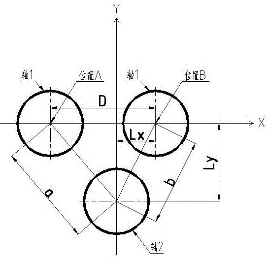
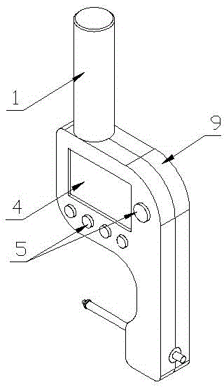
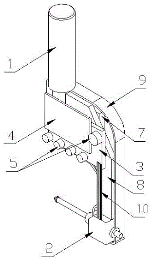
[0014] The digital display device for coaxiality deviation measurement includes a clamping handle 1, a displacement measuring device 2, a storage calculation chip 3, a display screen 4, a control button 5, a laser initial positioning device 6, a power supply 7, a device support frame 8, a housing 9, a connection Line 10. The distance parameter D and formulas 1 and 2 are stored in the storage calculation chip 3:

[0015] Formula 1

[0016] Formula 2

[0017] Wherein the D value can be displayed by the display screen 4 and the value can be adjusted by the control button, so as to adapt to measuring shafts or pins with different diameters. The digital display device for coaxiality deviation measurement is clamped on the main shaft 11 of the machine tool through the clamping handle 1. The laser initial positioning device 6 can emit a laser beam and irradiate the end surface of the shaft or pin 12 fixed on the workpiece 13 for Preliminary rough positioning of the machine...

Embodiment approach 2

[0019] Referring to Embodiment 1, the difference is that the displacement measuring device is replaced by a laser displacement measuring device.

Embodiment approach 3

[0021] Referring to Embodiment 1, the difference is that the displacement measuring device is replaced by a laser distance measuring device, and the distance between the central axis of the machine tool spindle and the central axis of the shaft or pin is directly measured by the laser distance measuring device.


PUM


Abstract

The invention relates to a coaxiality deviation measurement digital display device and a coaxiality deviation calculation method. The distances between the central axis of one axis in two different positions and the central axis of another axis and the distance between the two positions are utilized to calculate to obtain coaxiality deviation values of the two axes in a given coordinate system. The coaxiality deviation measurement digital display device mainly comprises a measurement device, a storage calculation chip and a display screen, wherein distance parameters and calculation formulas are stored in the storage calculation chip. By using the coaxiality deviation measurement digital display device and the coaxiality deviation calculation method, the problem of the adjustment of the coaxiality between the two axes of which the central axes are parallel is mainly solved. The distances a and b between the central axis of the axis 1 in the two different positions A and B and the central axis of the axis 2 are measured, and the distance D between the two different positions of the axis 1 is given, so as to derive a formula 1 and a formula 2 (see the specification). Two distance values Lx and Ly, i.e. the distance values, in the coordinate system formed by a straight line X which passes the two different positions A and B of the axis 1 and a straight line Y which passes the axis 2 and is perpendicular to the straight line X, can be calculated by utilizing the formulas. Thus, the coaxiality deviation values Lx and Ly of the axes 1 and 2 in the given coordinate system can be obtained.

Description

technical field [0001] The invention relates to a measuring digital display device and a calculation method, in particular to a digital display device for measuring coaxiality deviation and a calculation method for coaxiality deviation. Background technique [0002] In the prior art, the well-known technology is to use lever dial indicator, digital display dial indicator, dial indicator, laser displacement sensor to accurately measure the displacement value; the laser distance sensor can measure the precise distance between the measured object and distance. For the adjustment of the coaxiality between the two shafts, the known method is to use a lever gauge or a dial gauge, and the dial gauge is fixed on one of the shafts by a magnetic gauge seat, a bracket or other means, and then the detection gauge is made by rotating the shaft. The detection head measures the outer circle of another axis 360 degrees, and adjusts the coaxiality according to the reading deviation of the m...

Claims


Application Information

Patent Timeline
Patent Type & Authority Applications(China)
IPC IPC(8): B23Q17/00B23Q17/24G01B5/252G01B11/27
CPCB23Q17/2419B23Q17/2275
Inventor 鲁玉琼
Owner 鲁玉琼
Why Eureka
Try Eureka