
Crane for electric tower

A technology for cranes and power towers, applied in the field of cranes for power towers, can solve the problems of occupying large site resources, high use costs, and high construction costs, and achieve the advantages of improving construction quality and efficiency, strong site adaptability, and reducing construction costs. Effect

Inactive Publication Date: 2015-02-18
国网山东梁山县供电公司 +1
View PDF6 Cites 1 Cited by
  • Summary
  • Abstract
  • Description
  • Claims
  • Application Information

AI Technical Summary

Problems solved by technology

[0002] At present, in the erection of high-voltage transmission towers, due to their high height, the raw materials need to be transported to the sky with the help of lifting equipment. At present, because there is no such equipment used in the construction of power towers, large cranes are usually used in construction. and other equipment, but the use of large cranes requires a large site resource, so it cannot be used in areas with small construction sites such as mountains. At the same time, its use cost is relatively high, thus causing a lot of inconvenience and construction The problem of high cost, and when large cranes and other equipment cannot be used, construction personnel often need to rely on manpower to lift and transport raw materials, the work intensity is huge and the efficiency is not high, which seriously affects the construction and maintenance of power poles and towers.

Method used


Image

  • Crane for electric tower

Examples


Embodiment Construction

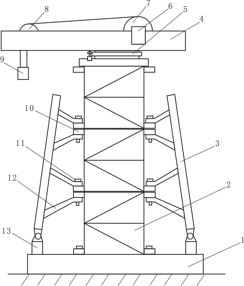
[0007] Now refer to the attached figure 1 , specifically described as follows in conjunction with the embodiment: a crane for a power tower includes a foundation foundation 1, a support column, a tower body standard section 2, a boom 4, a steering mechanism 5, a support wheel 8, a strand wheel 7, and a driving device 6. Suspension hook 9, backguy, reinforced beam and adjustment support 13. The support column is connected with the foundation 1 by bolts, and the support column is composed of at least two tower body standard sections, and the left and right sides of the upper and lower ends of the tower body standard section 2 are respectively provided with connecting ears 10, and connecting through holes are arranged in the connecting ears 10, The tower body standard sections 2 of two adjacent sections are fixedly connected through the connection through holes by bolts, and reinforced beams are respectively arranged on both sides of the supporting columns, and the reinforced bea...


PUM


Abstract

The invention discloses a crane for an electric tower. The crane for the electric tower comprises a foundation, a support column, tower body standard knots, a crane arm, a steering mechanism, a support wheel, a stranded wire wheel, a driving device, a lifting hook, a stay wire, intensifying beams and adjusting supports, wherein the support column is connected with the foundation by a bolt; the support column is composed of at least two tower body standard knots; connecting lugs are respectively arranged at the left side and the right side of the upper and lower ends of the tower body standard knots and are internally connected with connecting through holes; two adjacent tower body standard knots are fixedly connected by bolts via passing through the through holes; the intensifying beams are respectively arranged at two sides of the support column; the upper end of the support column is provided with the crane arm; the front end of the upper surface of the crane arm is provided with the support wheel, and the rear end of the upper surface of the crane arm is provided with the stranded wire wheel and the driving device; the stranded wire wheel is provided with a stay wire which droops naturally after passing by the support wheel; the front end of the stay wire is provided with a lifting hook; the crane arm is connected with the support column via the steering mechanism. The crane for the electric tower is stable and light in structure, can lower the labor intensity, and can improve the construction quality and efficiency effectively.

Description

technical field [0001] The invention belongs to the field of electric appliances, in particular to a crane for electric towers. Background technique [0002] At present, in the erection of high-voltage transmission towers, due to their high height, the raw materials need to be transported to the sky with the help of lifting equipment. At present, because there is no such equipment used in the construction of power towers, large cranes are usually used in construction. and other equipment, but the use of large cranes requires a large site resource, so it cannot be used in areas with small construction sites such as mountains. At the same time, its use cost is relatively high, thus causing a lot of inconvenience and construction The problem of high cost, and when large cranes and other equipment cannot be used, construction personnel often need to rely on manpower to lift and transport raw materials. The work intensity is huge and the efficiency is not high, which seriously af...

Claims


Application Information

Patent Timeline
IPC IPC(8): B66C23/16
CPCB66C23/166B66C23/62
Inventor 高祥银邵玉峰李来春张靳
Owner 国网山东梁山县供电公司
Learn More