
A kind of crane for power tower

A technology of power towers and cranes, which is applied in the field of power transmission and transformation, can solve the problems of occupying large site resources, high construction costs, and high work intensity, and achieve the effects of improving construction quality and efficiency, reducing construction costs, and having a stable and light structure

Active Publication Date: 2015-08-19
STATE GRID CORP OF CHINA +1
View PDF6 Cites 0 Cited by
  • Summary
  • Abstract
  • Description
  • Claims
  • Application Information

AI Technical Summary

Problems solved by technology

[0002] At present, in the erection of high-voltage transmission towers, due to their high height, the raw materials need to be transported to the sky with the help of lifting equipment. At present, because there is no such equipment used in the construction of power towers, large cranes are usually used in construction. and other equipment, but large cranes need to occupy large site resources when used, so they cannot be used in areas with small construction sites such as mountains. The problem of high cost, and when large cranes and other equipment cannot be used, construction personnel often need to rely on manpower to lift and transport raw materials, the work intensity is huge and the efficiency is not high, which seriously affects the construction and maintenance of power poles and towers.

Method used


Image

  • A kind of crane for power tower
  • A kind of crane for power tower

Examples


Embodiment Construction

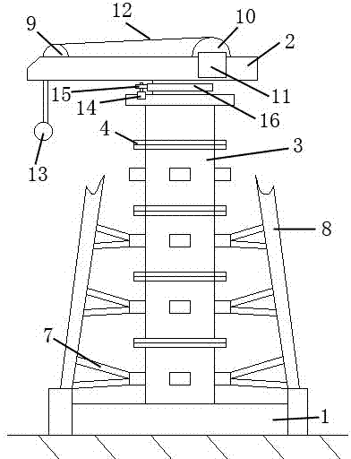
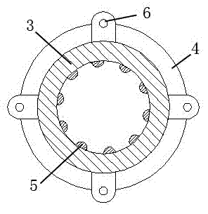
[0011] Such as figure 1 and 2 As shown, a crane for power poles and towers, the crane for power poles and towers is composed of a chassis plate 1, a support column, a lifting arm 2 and a strengthening beam, and the support column and the upper surface of the chassis plate 1 are connected by bolts. The support column is composed of at least two sections of cylinder 3 and connected by bolts. The cylinder 3 is a hollow cylindrical structure, wherein the two ends of the cylinder 3 are provided with connecting flanges 4, and the inner surface of the cylinder 3 is evenly distributed with the axis of the cylinder. Parallel reinforcing protrusions 5, the cross section of which is arc-shaped, at least four hinged holes 6 are partially provided on the outer surface of the column body 3, and the reinforcing beam is composed of at least two supporting arms 7, wherein the supporting arms 7. One end is hinged and the included angle is 15°-120°. The hinged end of the reinforced beam support...


PUM


Abstract

The invention discloses a crane for an electric power tower. The crane for the electric power tower is composed of a chassis disc, supporting pillars, a lifting arm and a strengthening beam, wherein the supporting pillars are connected with the upper surface of the chassis disc through bolts, and the supporting pillars are composed of at least two cylinders and are connected with the two cylinders through the bolts; the cylinders are of hollow cylindrical structures, the two ends of the cylinders are provided with connecting flange plates, and strengthening bulges are uniformly distributed on the inner surfaces of the cylinders and are parallel with the axes of the cylinders; the sections of the strengthening bulges are arc shapes, part of the outer surface of each strengthening bulge is provided with at least four hinging holes, and the strengthening beam is composed of at least two supporting arms; hinging ends of the supporting arms of the strengthening beam are in hinge joint with the hinging holes of the cylinders, and the other ends of the supporting arms of the strengthening beam are connected with the electric power tower; the lifting arm is a hydraumatic telescopic arm, and the lifting arm is connected with the cylinders through a steering mechanism. The crane provided by the invention has the advantages that the structure is stable and portable, compared with the traditional lifting equipment, the field adaptive capacity is strong, the coordination of the crane and site operation is tight, the construction cost and labor intensity of builders are greatly reduced, and the construction quality and efficiency are improved.

Description

technical field [0001] The invention relates to a crane for power poles and towers, which belongs to the field of power transmission and transformation. Background technique [0002] At present, in the erection of high-voltage transmission towers, due to their high height, the raw materials need to be transported to the sky with the help of lifting equipment. At present, because there is no such equipment used in the construction of power towers, large cranes are usually used in construction. and other equipment, but large cranes need to occupy large site resources when used, so they cannot be used in areas with small construction sites such as mountains. The problem of high cost, and when large cranes and other equipment cannot be used, construction personnel often need to rely on manpower to lift and transport raw materials. The work intensity is huge and the efficiency is not high, which seriously affects the construction and maintenance of power poles and towers. Conte...

Claims


Application Information

Patent Timeline
Patent Type & Authority Patents(China)
IPC IPC(8): B66C23/16
Inventor 冯振保
Owner STATE GRID CORP OF CHINA
Learn More