Sewing device for hot-melting strip clamped between folded edges of policeman uniform cuff

A technology of flanging and hot-melting, applied in the field of garment processing, can solve the problems of unevenness, reduced work efficiency, time-consuming and labor-intensive, etc., and achieves the effect of in-place flanging size, ensuring stability and accurate positioning.

Active Publication Date: 2015-02-18
JIHUA 3534 CLOTHING
View PDF9 Cites 7 Cited by
  • Summary
  • Abstract
  • Description
  • Claims
  • Application Information

AI Technical Summary

Problems solved by technology

[0002] For the production of armed police uniforms, there are certain requirements for the cuffs. It is required to leave a 3.5 cm folded edge in the cuffs, and this folded edge also has a 1 cm folded edge, that is, it needs to be folded twice. , in the specific operation, you first need to fold the cuff inward by 4.5 cm, and then fold the 4.5 cm edge and then fold it in the opposite direction by 1 cm, so that a 1 cm edge will be formed. The 3.5 cm folded edge, and it is also required to add a hot melt strip with a width of 1 cm between the second 1 cm folded edge and the first 3.5 cm folded edge. The first folded edge is sewn together with the hot-melt strip in the middle, and then ironed with an electric iron after processing. The operation is to fold the edge with a simple template tool, then put the hot melt strip on the edge of the folded edge, and then fold it together with the hot melt strip. This operation is time-consuming and laborious, and it is difficult to align the hot melt strip with the edge. The hot-melt strip is exposed and the elasticity is uneven, which not only reduces the work efficiency, but also does not guarantee the quality of the cuffs made

Method used


Image

  • Sewing device for hot-melting strip clamped between folded edges of policeman uniform cuff
  • Sewing device for hot-melting strip clamped between folded edges of policeman uniform cuff
  • Sewing device for hot-melting strip clamped between folded edges of policeman uniform cuff

Examples


Embodiment Construction

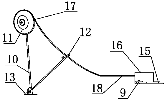
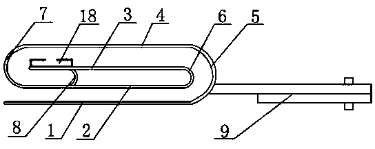
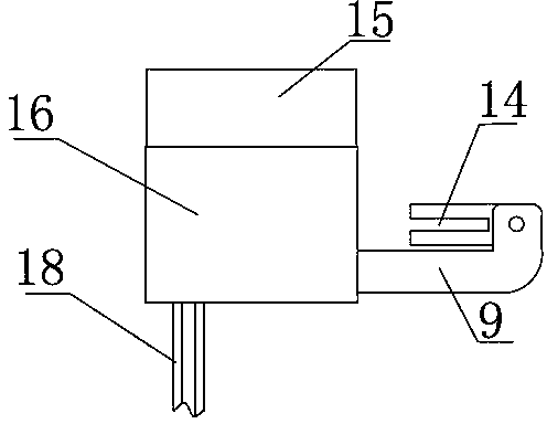
[0015] like figure 1 , figure 2 and image 3 Shown: a sewing device for clamping hot-melt strips at the folded edge of police uniform cuffs, including a hemming nozzle 16, a guide slot 18 for guiding the hot-melt strip 17 and a storage rack for the hot-melt strip. The nozzle 16 includes the first layout board 1, the second layout board 2, the third layout board 3 and the fourth layout board 4 arranged in sequence from top to bottom, the four layout boards are evenly spaced from each other and horizontal, and the four layout boards are The layout panels are aligned up and down, the right end of the first layout panel 1 and the right end of the fourth layout panel 4 are connected by the first arc-shaped plate 5, and the right end of the second layout panel 2 and the right end of the third layout panel 3 are connected by The second arc-shaped plate 6 is connected, the left end of the second cloth plate 2 and the left end of the fourth cloth plate 4 are connected through the th...


PUM


Abstract

The invention discloses a sewing device for a hot-melting strip clamped between the folded edges of a policeman uniform cuff. The sewing device comprises a folded edge nozzle, a strip guiding groove and a hot-melting strip storage rack, wherein the folded edge nozzle comprises four cloth plates which are arranged in sequence from top to bottom; the right end of the first cloth plate is connected with that of the fourth cloth plate through a first arc-shaped plate; the second cloth plate is connected with the third cloth plate through a second arc-shaped plate; the left end of the second cloth plate is connected with that of the fourth cloth plate through a third arc-shaped plate; a fourth arc-shaped plate is connected between the second cloth plate and the third cloth plat; the strip guiding groove is arranged on the third cloth plate; the head end of the strip guiding groove is connected with the hot-melting strip storage rack in a bearing manner; a fixing rack is arranged on one side of the folded edge nozzle. When used for sewing the cuff, the sewing device is accurate in positioning and convenient to operate and improves the sewing quality.

Description

technical field [0001] The invention relates to the technical field of garment processing. Background technique [0002] For the production of armed police uniforms, there are certain requirements for the cuffs. It is required to leave a 3.5 cm folded edge in the cuffs, and this folded edge also has a 1 cm folded edge, that is, it needs to be folded twice. , in the specific operation, you first need to fold the cuff inward by 4.5 cm, and then fold the 4.5 cm edge and then fold it in the opposite direction by 1 cm, so that a 1 cm edge will be formed. The 3.5 cm folded edge, and it is also required to add a hot melt strip with a width of 1 cm between the second 1 cm folded edge and the first 3.5 cm folded edge. The first folded edge is sewn together with the hot-melt strip in the middle, and then ironed with an electric iron after processing. The operation is to fold the edge with a simple template tool, then put the hot melt strip on the edge of the folded edge, and then fo...

Claims


Application Information

Patent Timeline
Patent Type & Authority Applications(China)
IPC IPC(8): D05B35/00
CPCD05B35/06D05B35/08
Inventor 支春伟李彩娟
Owner JIHUA 3534 CLOTHING
Why Eureka
Try Eureka