Eureka AIR delivers breakthrough ideas for toughest innovation challenges, trusted by R&D personnel around the world.

Improved connecting structure for front push rod and rear push rod of support

A connecting device and push rod technology, which is applied to mine roof supports, mining equipment, earth-moving drilling, etc., can solve the problems of unreliable connection, large force on the front and rear push rods, and difficult installation, so as to solve the inconvenient installation, disassembly and maintenance. , The effect of reducing installation space, convenient disassembly and maintenance

Inactive Publication Date: 2015-02-18
GUIZHOU PANJIANG MINING MACHINERY
View PDF5 Cites 0 Cited by
  • Summary
  • Abstract
  • Description
  • Claims
  • Application Information

AI Technical Summary

Problems solved by technology

[0002] The front and rear push rods of the existing bracket are connected. The front push rod is provided with a frame structure with front and rear levels and horizontal holes, and the rear push rod is provided with a thicker single connecting ear. Penetrate from the horizontal side into the connecting ear hole for connection and fixation. Because the pin shaft is long, there must be enough space for the pin shaft when penetrating in. However, the span width of the bracket installation push rod is limited, which makes installation difficult, and the installation is large. For the installation of parts, it is necessary to continuously adjust the position of the front and rear push rods to realize the alignment of the through holes on the connecting ears of the front and rear push rods. Broken and damaged, inconvenient maintenance, unreliable connection

Method used


Image

  • Improved connecting structure for front push rod and rear push rod of support
  • Improved connecting structure for front push rod and rear push rod of support
  • Improved connecting structure for front push rod and rear push rod of support

Examples


Embodiment Construction

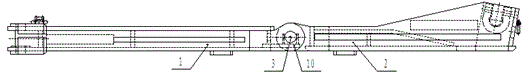
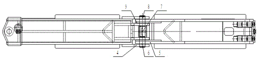
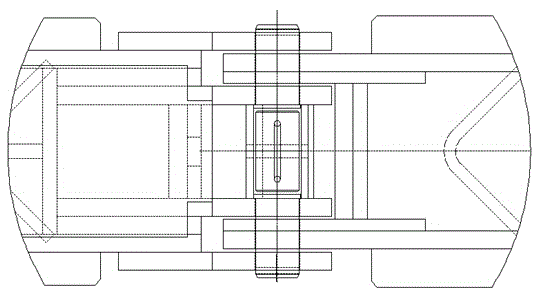
[0015] Such as Figure 1~4 As shown, an improved connection device for the front and rear push rods of a bracket, including a front push rod 1 and a rear push rod 2, the right end of the front push rod 1 is provided with double ears 3 vertically arranged up and down, and the left end of the rear push rod 2 is provided with The double ears 4 arranged vertically up and down, the front push rod 1 and the rear push rod 2 are connected vertically through the through holes on the double double ears 4 and double ears 5 through the pin shaft 3, and the double ears 5 are embedded in the double double ears 4 Among them, the pin shaft 3 adopts three-stage detachable connection, that is, the first pin shaft 6, the stop pin 7 and the second pin shaft 8 in sequence, the stop pin 7 is fixed in the groove of the support 10, and the The first pin shaft 6 and the second pin shaft 8 are placed in the holes of the double ears 4 and the double ears 5, and the segmented pin shaft 3 is installed ver...


PUM


Abstract

The invention discloses an improved connecting structure for a front push rod and a rear push rod of a support, which comprises the front push rod and the rear push rod; double dual lugs which are vertically arranged are arranged on the right end of the front push rod, double lugs which are vertically arranged are arranged on the left end of the rear push rod, the front push rod is connected with the rear push rod through pin shafts vertically penetrating through through holes, the pin shafts adopt three-section detachable connection, i.e. a first pin shaft, a spacing pin and a second pin shaft, the spacing pin is fixed in the groove of a supporting base, and the first pin shaft and the second pin shaft are placed in the holes of the double dual lugs and the double lugs. Since the improved connecting structure adopts the vertical and downward sectioned pin shaft mounting method and the open type connecting double-lug structure, the front push rod and the rear push rod can be conveniently connected and assembled, the space occupied by assembly is reduced, the problems of inconvenient assembly, disassembly and maintenance, complex structure and joint damage caused by poor strength and rigidity in the prior art are effectively solved, the high rigidity and strength of connection between the front push rod and the rear push rod is realized, the joints cannot be easily damaged, and moreover, the improved connecting structure has the characteristics of simple and compact structure and convenience in disassembly and maintenance.

Description

technical field [0001] The invention belongs to the field of coal machinery, in particular to an improved connection device for front and rear push rods of a bracket which is easy to install and operate. Background technique [0002] The front and rear push rods of the existing bracket are connected. The front push rod is provided with a frame structure with front and rear levels and horizontal holes, and the rear push rod is provided with a thicker single connecting ear. Penetrate from the horizontal side into the connecting ear hole for connection and fixation. Because the pin shaft is long, there must be enough space for the pin shaft when piercing in. However, the span width of the bracket installation push rod is limited, which makes installation difficult, and the installation is large. For the installation of parts, it is necessary to continuously adjust the position of the front and rear push rods to realize the alignment of the through holes on the connecting ears o...

Claims


Application Information

Patent Timeline
Patent Type & Authority Applications(China)
IPC IPC(8): E21D23/04
CPCE21D23/04
Inventor 陈朝晖任芸毕碧
Owner GUIZHOU PANJIANG MINING MACHINERY
Why Eureka
Eureka Blog
Learn More