Single valve expander system capable of realizing isothermal expansion and method
An isothermal expansion and expander technology, applied in mechanical equipment, engine components, machines/engines, etc., can solve problems such as affecting the normal operation of the machine, increasing costs, and frosting of the exhaust holes, and achieves the improvement of output power per unit of working fluid, The effect of reducing the number of expansion stages and improving the overall efficiency
- Summary
- Abstract
- Description
- Claims
- Application Information
AI Technical Summary
Problems solved by technology
Method used
Image
Examples
Embodiment 1
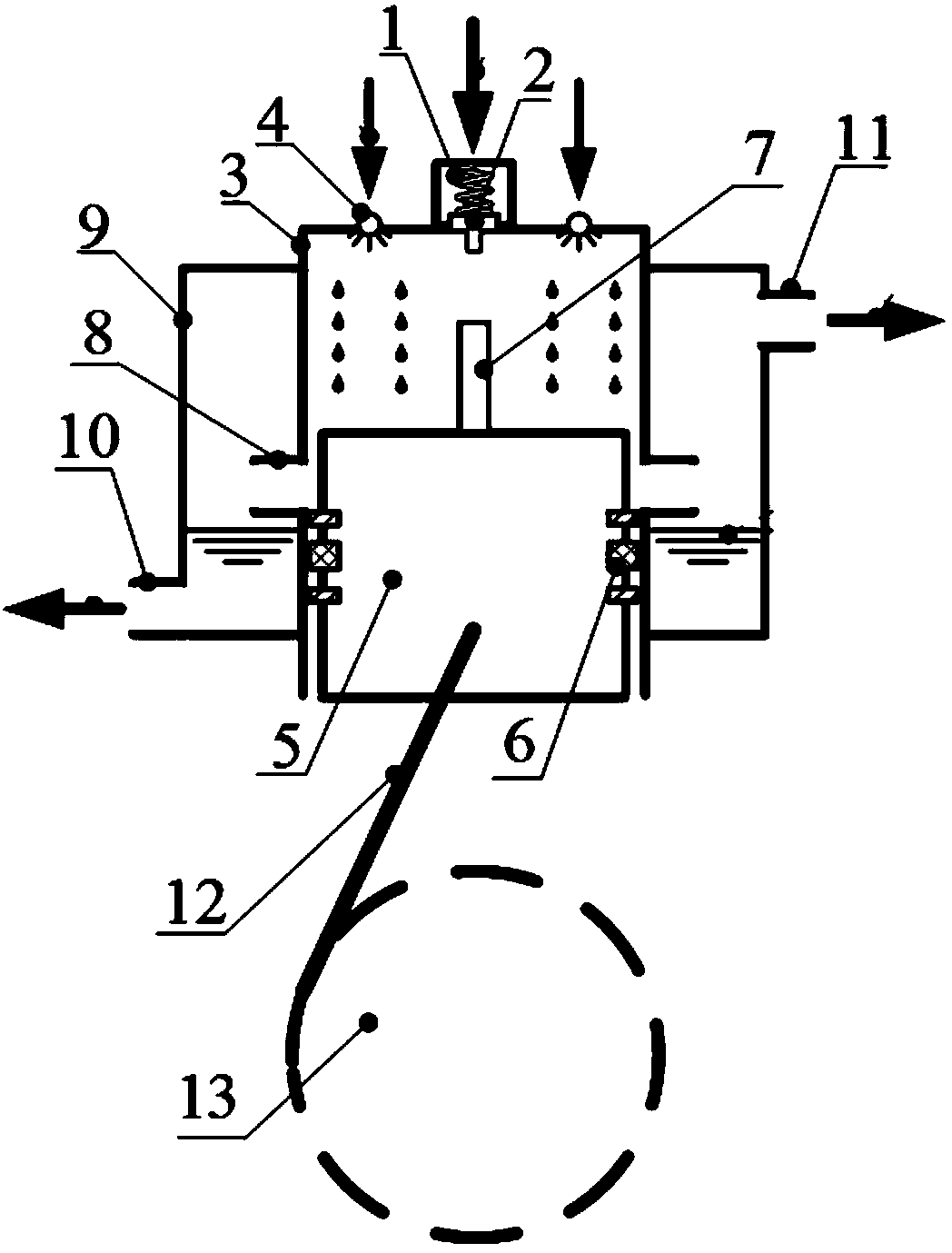
[0029] figure 1It is a structural schematic diagram of Embodiment 1 of the isothermal expansion single-valve expander system and method of the present invention. The single-valve isothermal expander includes a piston 5, a cylinder 3 and a crank-link mechanism. The piston 5 is slidably installed in the cylinder 3. The crank-link mechanism includes a connecting rod 12 and a crank 13. One end of the connecting rod 12 is connected to the piston 5, and the other end is connected to the The crank 13 is connected, and the intake valve 2 and the annular injector 4 are installed on the top of the cylinder 3. The intake valve 2 communicates with the external high-pressure gas working medium source, and the annular injector 4 communicates with the external heating medium source system, which is used to transfer the heating medium Atomize or form foam and inject into cylinder 3 with a certain mass flow. An exhaust hole 8 is provided on the side wall of the cylinder near the bottom dead c...
Embodiment 2
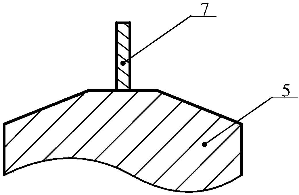
[0031] figure 2 It is a structural schematic diagram of embodiment 2 of the present invention, in the figure 5 is a part of the piston body, and mainly the top part of the piston, 7 is the ejector rod, the present embodiment has listed the shape of the top of the piston 5, given in embodiment 1 The top of the piston is flat. Such as figure 2 As shown, the top of the piston can also be a slope, and the angle between it and the plane is greater than 0 degrees. When the piston runs to the bottom dead center, this structure facilitates the timely discharge of the liquid accumulated on the piston surface to the exhaust buffer. Inside cavity 9.
Embodiment 3
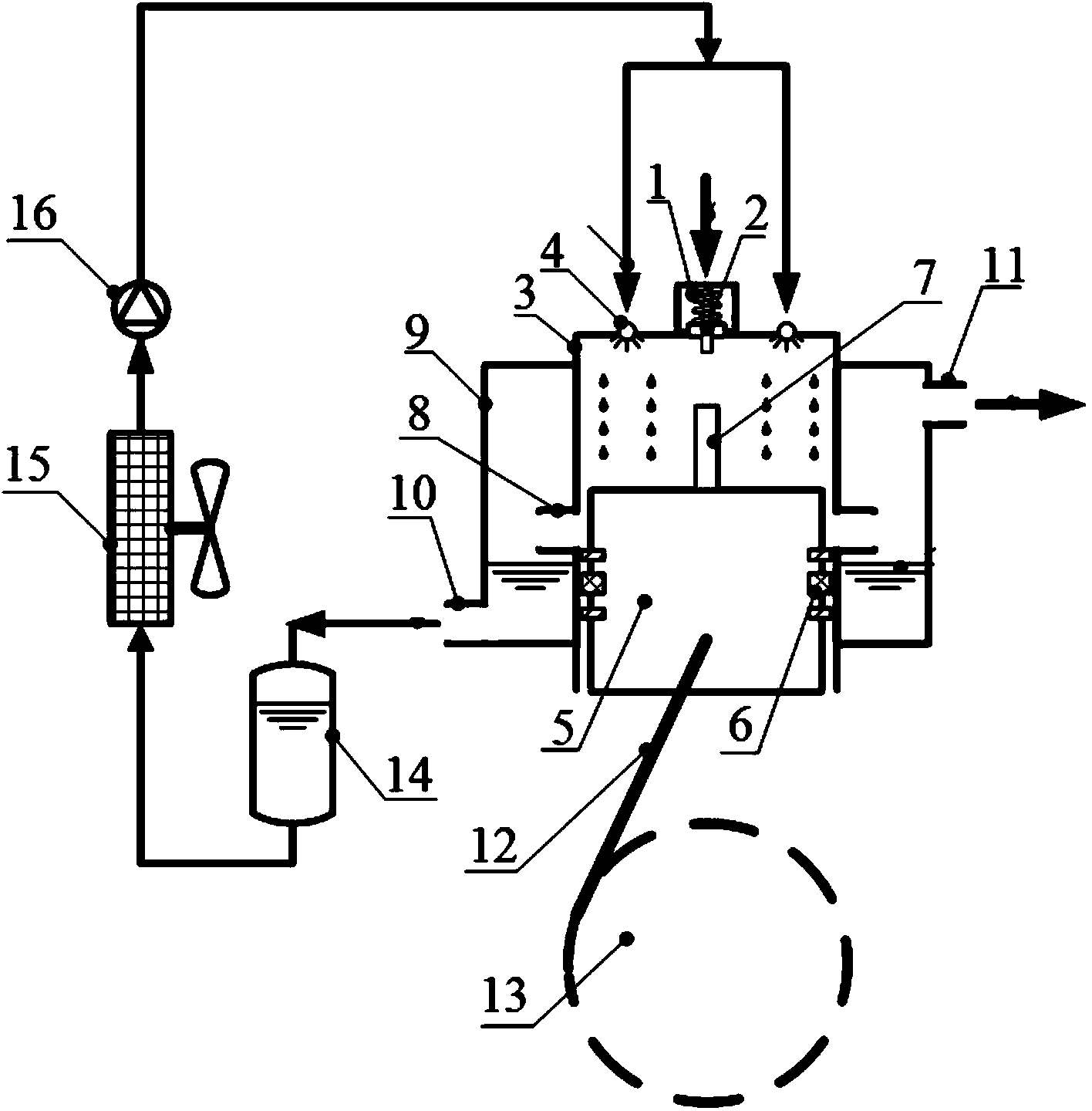
[0033] image 3 It is a schematic structural diagram of Embodiment 3 of the present invention, and its main structure is the same as that of Embodiment 1. The difference is that the flow loop of the heating medium is given in this embodiment. The heating medium enters the expander cylinder 3 at ambient temperature, goes through the expansion process of the expander, and is discharged, and its temperature drops, and the discharged heating medium enters the liquid tank 14, and then passes through an air cooler 15, where the ambient temperature is used to heat the fluid medium , and then pressurize through a liquid pump 16, and inject it into the cylinder again. It should be noted that Embodiment 2 can also be used in this embodiment; if the heating medium is sprayed into the cylinder in the form of foam, a special additive such as propylene glycol, low-boiling alkanes or fluorocarbons has been added to the heating medium compounds etc.
PUM
 Abstract
Description
Claims
Application Information
 - R&D
- Intellectual Property
- Life Sciences
- Materials
- Tech Scout
- Unparalleled Data Quality
- Higher Quality Content
- 60% Fewer Hallucinations
Browse by: Latest US Patents, China's latest patents, Technical Efficacy Thesaurus, Application Domain, Technology Topic, Popular Technical Reports.
© 2025 PatSnap. All rights reserved.Legal|Privacy policy|Modern Slavery Act Transparency Statement|Sitemap|About US| Contact US: help@patsnap.com


