Design method for non-clogging vortex-pump impeller with long and short edgefold blades

A design method and swirl pump technology, applied to parts, pumps, pump elements, etc. of pumping devices for elastic fluids, can solve energy waste, cannot effectively limit radial to axial circulation flow, and swirl flow Problems such as poor hydraulic performance of the pump

Inactive Publication Date: 2015-02-18
JIANGSU UNIV
View PDF5 Cites 15 Cited by
  • Summary
  • Abstract
  • Description
  • Claims
  • Application Information

AI Technical Summary

Problems solved by technology

However, the hydraulic performance of the swirl pump using this impeller is not good, and it cannot effectively limit the circular flow from radial to axial. Therefore, the lift and efficiency of the pump are greatly reduced, resulting in a serious waste of energy.

Method used


Image

  • Design method for non-clogging vortex-pump impeller with long and short edgefold blades
  • Design method for non-clogging vortex-pump impeller with long and short edgefold blades
  • Design method for non-clogging vortex-pump impeller with long and short edgefold blades

Examples


Embodiment Construction

[0037] The present invention will be further described below in conjunction with the accompanying drawings and specific embodiments, but the protection scope of the present invention is not limited thereto.

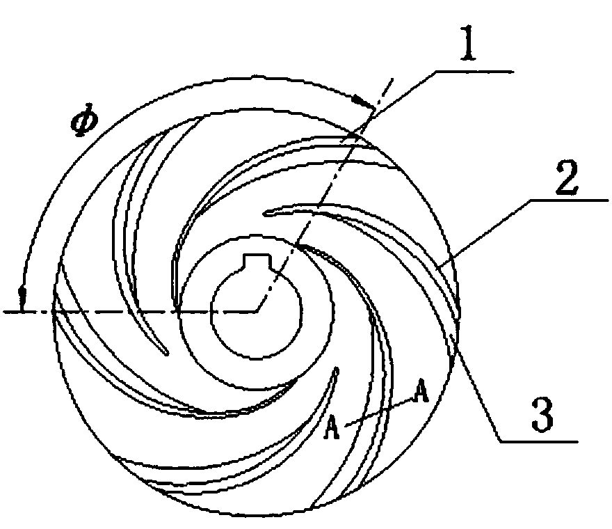
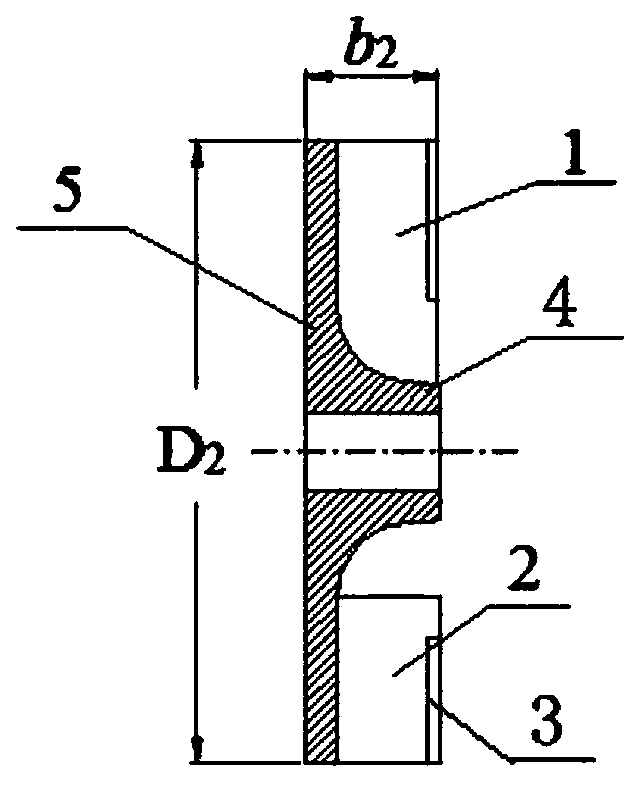
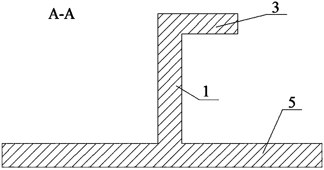
[0038] According to the design method of the non-clogging swirl pump impeller with long and short folded blades in the present invention, the impeller adopts a semi-open impeller with a rear cover plate 7, a hub 4 and blades, and the blades of the impeller include lengths of different lengths. The blade 1 and the short blade 2, the long blade 1 and the short blade 2 each have a folded edge 3 extending in a direction opposite to the rotation direction of the impeller. The impeller outer diameter D of the swirl pump impeller 2 , impeller outlet width b 2 , impeller inlet diameter D 1 , the total number of blades Z, the width of the volute without blade cavity L, the width of the folded edge 3 b 0 , blade wrap angle φ is obtained by the following formula:

[0039] ...


PUM


Abstract

The invention provides a design method for a non-clogging vortex pump impeller with long and short edgefold blades. The design method is characterized in that the impeller is a semi-open impeller; the blades of the impeller comprise long blades and short blades with different lengths; edgefolds extending in the direction opposite to the rotating direction of the impeller are arranged on the long blades and short blades; the impeller outer diameter of the vortex pump impeller is D2, the impeller outlet width is b2, the impeller inlet diameter is D1, the total number of the blades is Z, the volute bladeless cavity width is L, the edgefold width is b0, and the wrap angle of each blade is phi. The non-clogging vortex pump impeller with long and short edgefold blades, which is designed according to the design method provided by the invention has good hydraulic performance, can effectively reduce energy loss of circulation flow in a pump cavity, increase the passing rate of conveyed solid medium, and improve the efficiency of a vortex pump, and has a good reaction effect after trial use by a user, so that investment and energy sources can be effectively saved.

Description

technical field [0001] The invention relates to a hydraulic design method of a swirl pump, in particular to a design method of a non-blocking swirl pump impeller with long and short folded blades. Background technique [0002] The swirl pump is a kind of centrifugal pump, which is mostly used to pump complex media or fluids containing impurities. Because the blades are retracted into the blade chamber of the pump body and rotate, the internal flow of the swirl pump is quite complicated. When the impeller rotates, the energy of the medium is increased by the centrifugal force, and the medium entering the blades is pushed by the blades to move together with the impeller, making the worm Through flow and circulation flow are formed in the shell, and the hydraulic loss of the swirl pump is very large due to the existence of circulation flow. At present, the semi-open impeller used in the known swirl pump consists of a back cover, blades and a hub. However, the hydraulic perfor...

Claims


Application Information

Patent Timeline
Patent Type & Authority Applications(China)
IPC IPC(8): F04D29/22F04D29/24
CPCF04D29/22F04D29/242
Inventor 王秀礼朱荣生付强
Owner JIANGSU UNIV
Why Eureka
Try Eureka