A fingerprint lock for a safe deposit box
A safe deposit box and fingerprint technology, which is applied to non-mechanical transmission-operated locks, building locks, instruments, etc., can solve the problems of insecurity and inconvenience, and achieve the effect of high safety and convenient use.
- Summary
- Abstract
- Description
- Claims
- Application Information
AI Technical Summary
Problems solved by technology
Method used
Image
Examples
Embodiment 1
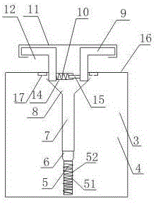
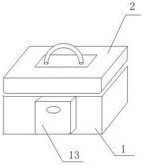
[0016] like figure 1 , figure 2 Shown, a kind of fingerprint lockset of safe deposit box comprises box body 1, box lid 2 that is hingedly connected with box body 1, and the upper end of a side wall of described box body 1 has rectangular parallelepiped groove 3, also includes and is arranged on rectangular parallelepiped concave The lock body 4 in the slot 3, the lock body 4 includes an electromagnet 5 and a connection block 6 connected with the electromagnet 5, the connection block 6 is made of non-magnetic material; it also includes a slider 7, the slider The block 7 is a cavity structure with an opening at the bottom, and the connecting block 6 is inserted in the cavity structure of the slider 7; the inside of the slider 7 is provided with a magnet, and the magnetism at the lower end of the slider 7 is opposite to that at the upper end of the electromagnet 5; It also includes a V-shaped seat 8 fixed on the upper end of the slider 7, and also includes two L-shaped lock bar...
Embodiment 2
[0019] In this embodiment, on the basis of Embodiment 1, the electromagnet 5 includes an iron core 51 and a coil 52 wound outside the iron core 51, and the coil 52 is connected to the output terminal of the power supply.
[0020] In this embodiment, the coil 52 is connected to the output end of the power supply. When the user's fingerprint is consistent with the fingerprint entered into the fingerprint identification system 13 before, the power supply will be connected, and the coil wound outside the iron core 51 will be energized. , the iron core 51 will generate electromagnetic force due to electromagnetic induction.
Embodiment 3
[0022] In this embodiment, on the basis of Embodiment 1 or Embodiment 2, the elastic element 10 includes a connecting rod 14, and the connecting rod 14 is a cavity structure, and also includes a sliding rod 15 slidably arranged in the cavity structure, and Including one end fixed on the bottom of the connecting rod 14, the other end is fixed on the spring on the slide bar 15; the connecting rod 14 is fixed on the vertical section of the left L-shaped lock bar 9, and the slide bar 15 is connected to the right L-shaped lock on the vertical section of rod 9.
[0023] In this embodiment, the spring is arranged in the cavity structure, and one end of the spring is fixed on the bottom of the connecting rod 14, and the other end is fixed on the sliding rod 15, thereby limiting the position of the spring, so that the spring is only in the horizontal position. direction to move.
PUM
 Abstract
Description
Claims
Application Information
 - R&D
- Intellectual Property
- Life Sciences
- Materials
- Tech Scout
- Unparalleled Data Quality
- Higher Quality Content
- 60% Fewer Hallucinations
Browse by: Latest US Patents, China's latest patents, Technical Efficacy Thesaurus, Application Domain, Technology Topic, Popular Technical Reports.
© 2025 PatSnap. All rights reserved.Legal|Privacy policy|Modern Slavery Act Transparency Statement|Sitemap|About US| Contact US: help@patsnap.com


