Supercharge Your Innovation With Domain-Expert AI Agents!

Electronic device

A technology for electronic devices and accommodating slots, which is applied to electrical components, electrical equipment casings/cabinets/drawers, casings/cabinets/drawer components, etc., and can solve problems such as laborious opening of the display

Active Publication Date: 2015-02-18
INVENTEC PUDONG TECH CORPOARTION +2
View PDF5 Cites 0 Cited by
  • Summary
  • Abstract
  • Description
  • Claims
  • Application Information

AI Technical Summary

Problems solved by technology

[0003] Taking notebook computers as an example, there are currently large-sized notebook computers on the market. If the friction force of the damping pivot is too large, the user needs to load the friction force of the damping pivot at the same time during the pivoting operation. and the weight of the display, so the user is more laborious when opening the display

Method used


Image

  • Electronic device
  • Electronic device
  • Electronic device

Examples


Embodiment Construction

[0018] The present invention will be described in further detail below in conjunction with the accompanying drawings and specific embodiments. Advantages and features of the present invention will be apparent from the following description and claims. It should be noted that the drawings are all in a very simplified form and use imprecise ratios, which are only used to facilitate and clearly assist the purpose of illustrating the embodiments of the present invention.

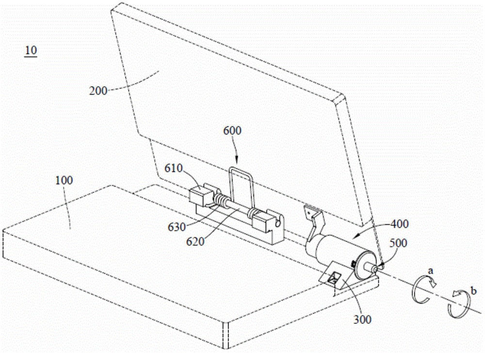
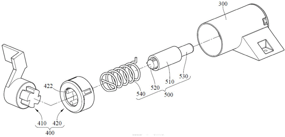
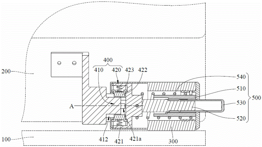
[0019] Please refer to Figure 1 to Figure 4 . figure 1 It is a three-dimensional schematic diagram of the electronic device according to the first embodiment of the present invention. figure 2 for figure 1 An exploded schematic diagram of the fixed seat, pivoting member, and detent assembly. Figure 3A for figure 1 partial sectional view. Figure 3B for figure 1 partial sectional view. Figure 4 for figure 2 A partially exploded schematic of the detent assembly.

[0020] Such as figure 1 and figu...


PUM


Abstract

An electronic device comprises a first base, a second base, a pivot component and a buffer unit. The second base is pivoted to the first base. The pivot component comprises a first ratchet unit and a second ratchet unit. The first ratchet unit is disposed on the second base. The second ratchet unit is slidably provided on the first base and has a meshing position and a releasing position. The buffer unit is provided between the first base and the second base and connected to the first base and the second base. When the second ratchet unit is at the meshing position, the second base can be unfolded relative to the first base in a single rotation direction through meshing of the first and second ratchet units; when the second ratchet unit is at the releasing position, the first and second ratchet units separate so that the second base reversely rotates and gets close to the first base.

Description

technical field [0001] The present invention relates to an electronic device, especially an electronic device pivoted through a ratchet. Background technique [0002] There are many items in daily life that use pivoting mechanisms, such as doors, windows, car rear-view mirrors or notebook computers, electronic dictionaries, personal digital assistants (PDAs), mobile phones and other electronic devices, all of which must rely on pivoting mechanism to achieve the function of rotating or switching the body. The pivoting mechanism generally has a rotating shaft and a gasket set, etc., and uses the friction force between the stator and the rotor (ie, the damping pivot) to offset the torsion force generated by the gravity of the body, so as to achieve the positioning effect during the rotation stroke. Therefore, the quality of the design of the pivoting mechanism will affect the convenience and reliability of the user's operation of the above-mentioned device. [0003] Taking no...

Claims


Application Information

Patent Timeline
Patent Type & Authority Applications(China)
IPC IPC(8): H05K5/02H05K5/00
Inventor 陈建仁蔡志宏黄健凯
Owner INVENTEC PUDONG TECH CORPOARTION
Features
  • R&D
  • Intellectual Property
  • Life Sciences
  • Materials
  • Tech Scout
  • Unparalleled Data Quality
  • Higher Quality Content
  • 60% Fewer Hallucinations
Learn More