Brake device

A braking device, braking surface technology, applied in the direction of brake type, brake actuator, mechanically driven drum brake, etc., can solve problems such as inability to exceed, the inability of the brake cam to rotate, etc.

Inactive Publication Date: 2015-02-18
TS TECH CO LTD
View PDF11 Cites 5 Cited by
  • Summary
  • Abstract
  • Description
  • Claims
  • Application Information

AI Technical Summary

Problems solved by technology

Once the rotating part on the output side rotates, the force applied to the brake cam by the rotating part on the output side which is in contact with the brake cam is mainly used as a force to press the brake cam against the outer ring, while the rotating part on the output side exerts a force on the brake cam. The rotational force of the movable cam cannot exceed the frictional force between the brake cam and the outer ring, so that the brake cam cannot rotate

Method used


Image

  • Brake device
  • Brake device
  • Brake device

Examples


Embodiment Construction

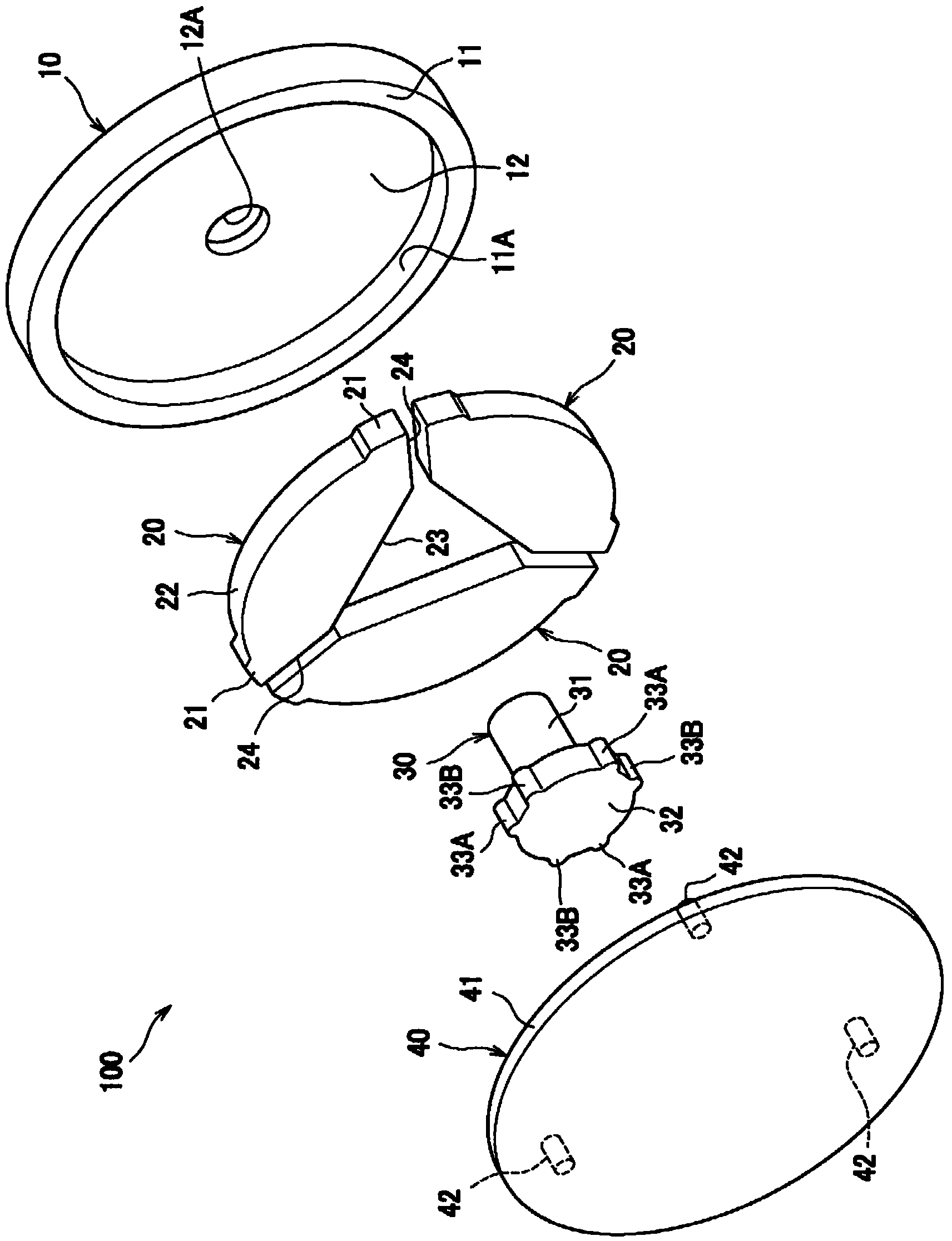
[0032] Hereinafter, specific embodiments of the present invention will be described in detail by referring to the drawings where appropriate. Such as figure 1 As shown, a brake device 100 according to an embodiment includes an outer ring 10 , a brake cam 20 , an output-side rotating member 30 and an input-side rotating member 40 .

[0033] The outer ring 10 includes an annular portion 11 having a certain thickness and a side wall 12 provided on one side of the annular portion 11 . The annular portion 11 has a cylindrical inner peripheral surface 11A (having a circular cross section). The side wall 12 has a through hole 12A formed therein at a position corresponding to the central axis of the inner peripheral surface 11A.

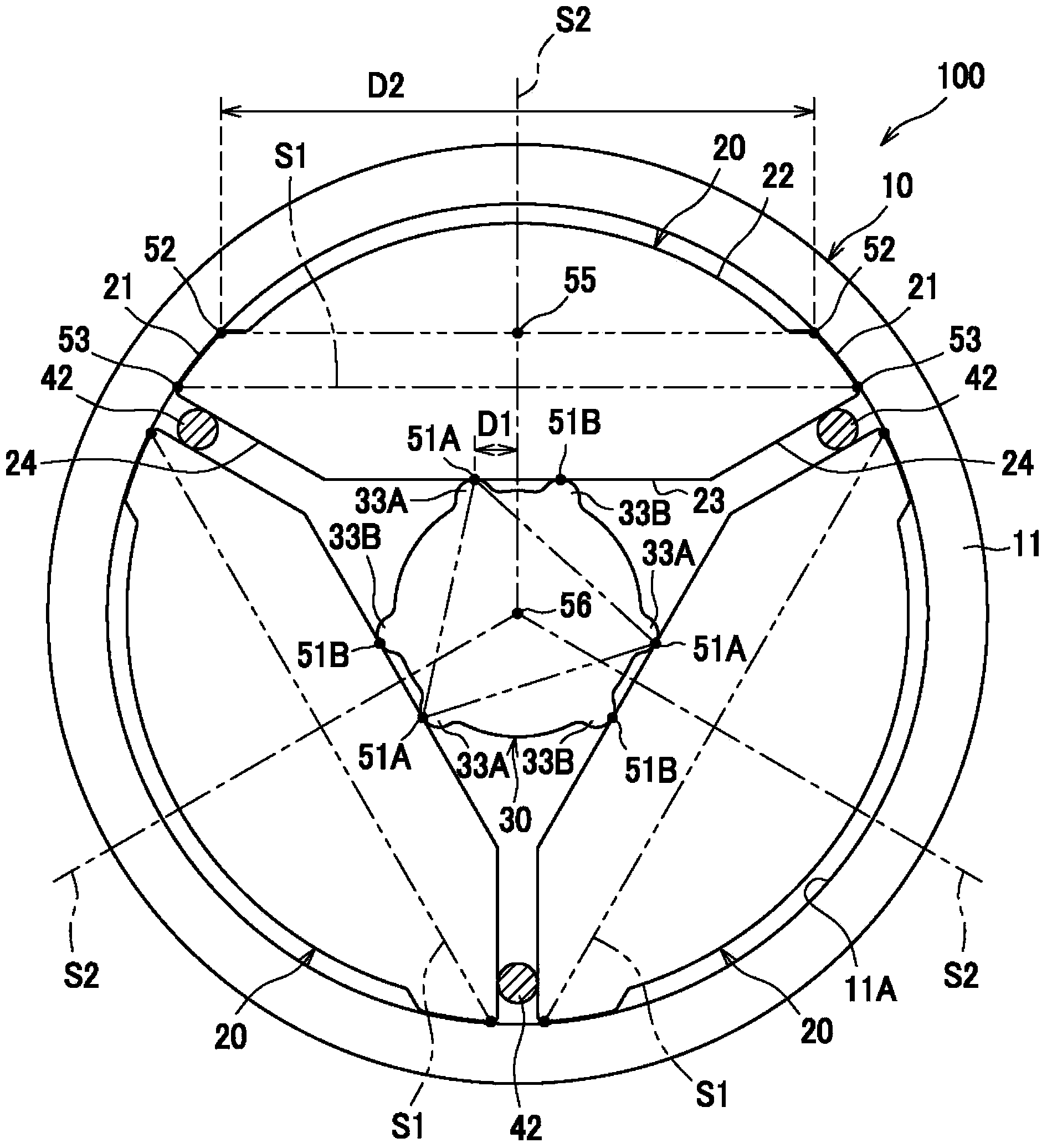
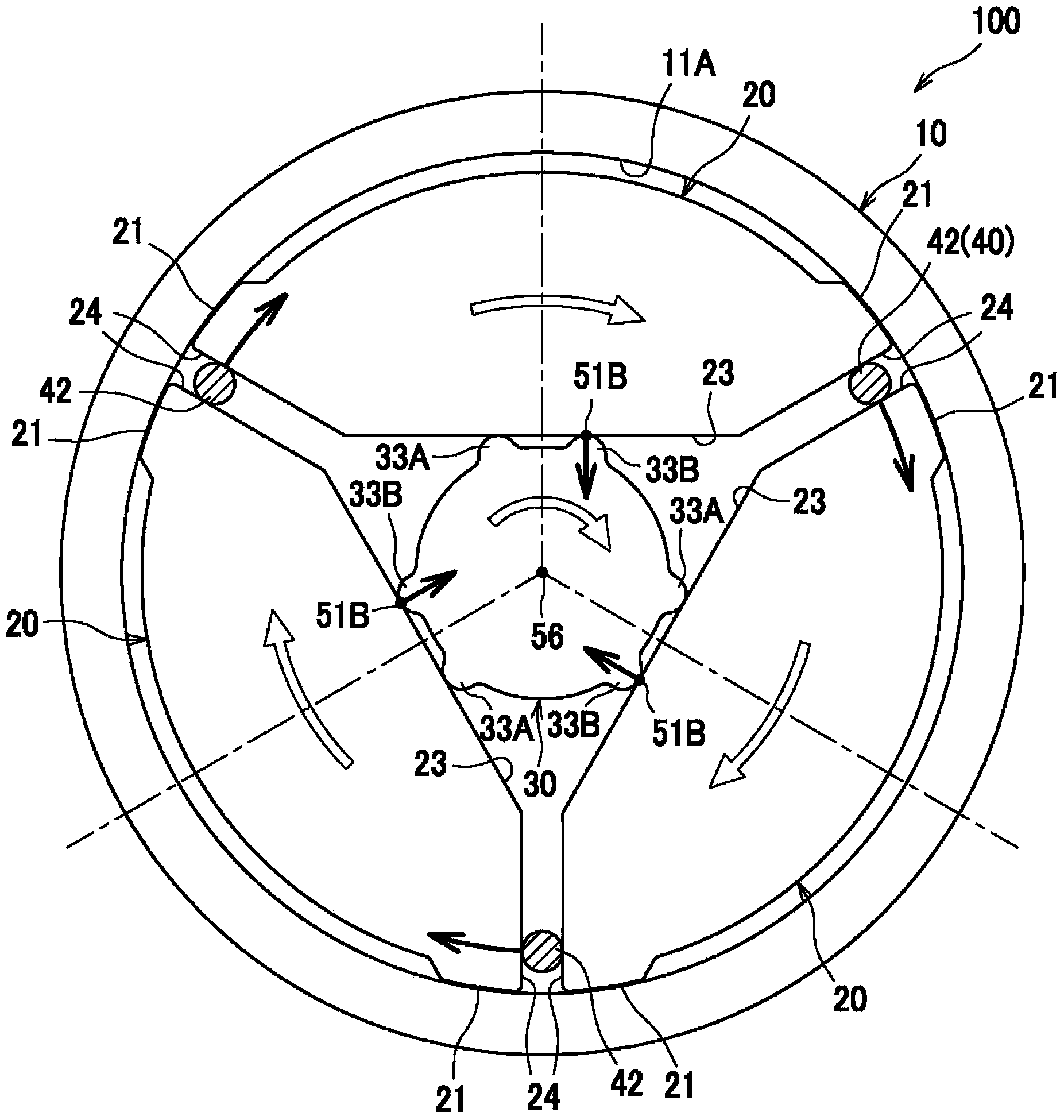
[0034] The brake cam 20 is a member for generating a braking force on its surface in contact with the outer ring 10 . Three detent cams 20 are arranged equidistantly on the inner side of the outer ring 10 in the circumferential direction. Each braking ca...


PUM


Abstract

A brake device is provided with: an outer ring (10) having a cylindrical inner peripheral surface (11A); at least two brake cams (20) disposed on the inside of the outer ring (10) so as to be arranged side by side in the circumferential direction and each having brake surfaces (21) which are located at both circumferential ends of the brake cam (20), the circumferential ends being located on the side facing the outer ring (10), and which can be in contact with the inner peripheral surface of the outer ring (10); and an output-side rotation member (30) disposed on the inside radially of the brake cams (20) and having contact sections (33A, 33B) capable of being in contact with the radially inner surfaces of the brake cams (20). The contact points (51A, 51B), where the contact sections and the brake cams (20) are in contact with each other, are located closer to the rotation axis (56) of the output-side rotation member (30) than a reference plane (S1) formed by connecting ends of the brake surfaces (21) located at both ends of the brake cam (20) corresponding to the contact points or are located on the reference plane (S1).

Description

technical field [0001] The invention relates to a brake device applied to a height adjustment mechanism of a vehicle seat or a similar seat. Background technique [0002] The specific setting of the brake device used in the height adjustment mechanism of the vehicle seat is as follows: the output shaft can be rotated under the action of the up and down swing of the lever arranged on the input side of the height adjustment mechanism of the seat, but when the seat is moved The output shaft is prevented from rotating when a downwardly biased force generated by the weight of the seat and the seat occupant is applied to the output shaft (Patent Document 1). [0003] In such a brake device, there are provided: an outer ring including a cylindrical inner peripheral surface, a plurality of brake cams (jaw members in patent documents) facing the inner peripheral surface, and The output-side rotary member (in Patent Document 1, a bolt with wings). The rotational action received by t...

Claims


Application Information

Patent Timeline
Patent Type & Authority Applications(China)
IPC IPC(8): F16D63/00B60N2/04B60N2/90
CPCF16D51/12F16D63/00B60N2/168B60N2/1889F16D67/00F16D41/082F16D43/02B60N2/938F16D65/22F16D2121/14F16D51/42F16D51/36F16D2125/30
Inventor 郭裕之
Owner TS TECH CO LTD
Why Eureka
Try Eureka