Antenna arrangement structure for vehicle communication apparatus

A communication device and antenna configuration technology, which is applied to antennas, leaky waveguide antennas, antenna parts, etc., can solve the problems of radio wave leakage, failure to detect the presence of mobile terminals inside the cabin, leakage, etc., and improve appearance Effect

Active Publication Date: 2015-02-18
HONDA MOTOR CO LTD
View PDF5 Cites 11 Cited by
  • Summary
  • Abstract
  • Description
  • Claims
  • Application Information

AI Technical Summary

Problems solved by technology

[0013] However, if the leaky coaxial cable is simply arranged inside the vehicle, only in an area where the signal transmitted from the first antenna cannot directly reach, the radio waves in the high frequency band transmitted from the leaky coaxial cable will also be transmitted from the vehicle. window leaking out of car
Even if such a leaky coaxial cable is adopted as the antenna of the electronic key system for a vehicle as described above, radio waves in the high-frequency band will leak out of the vehicle through the window, so the mobile terminal cannot be detected. The case that exists in the inside of the compartment

Method used


Image

  • Antenna arrangement structure for vehicle communication apparatus
  • Antenna arrangement structure for vehicle communication apparatus
  • Antenna arrangement structure for vehicle communication apparatus

Examples


Embodiment 1

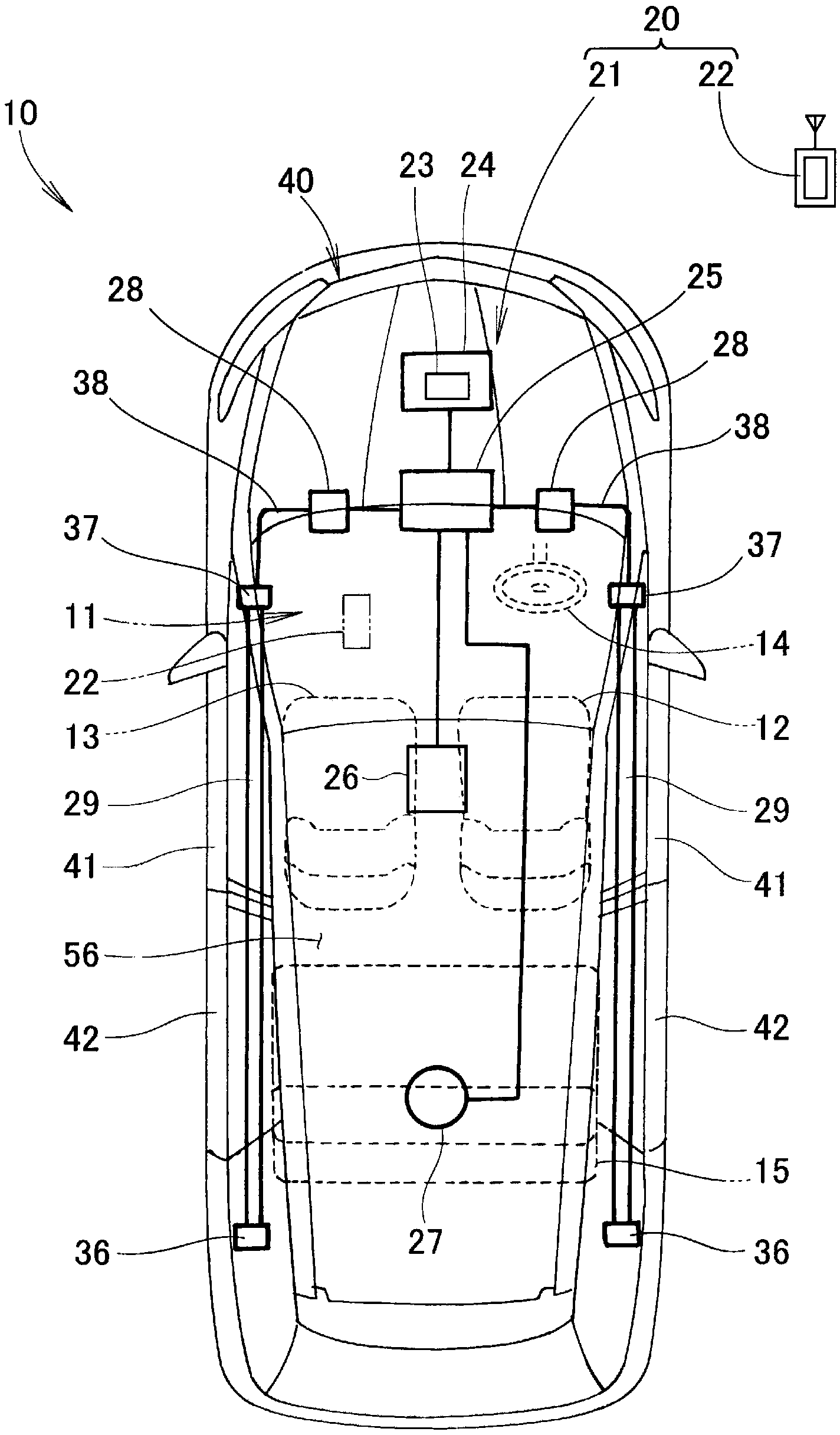
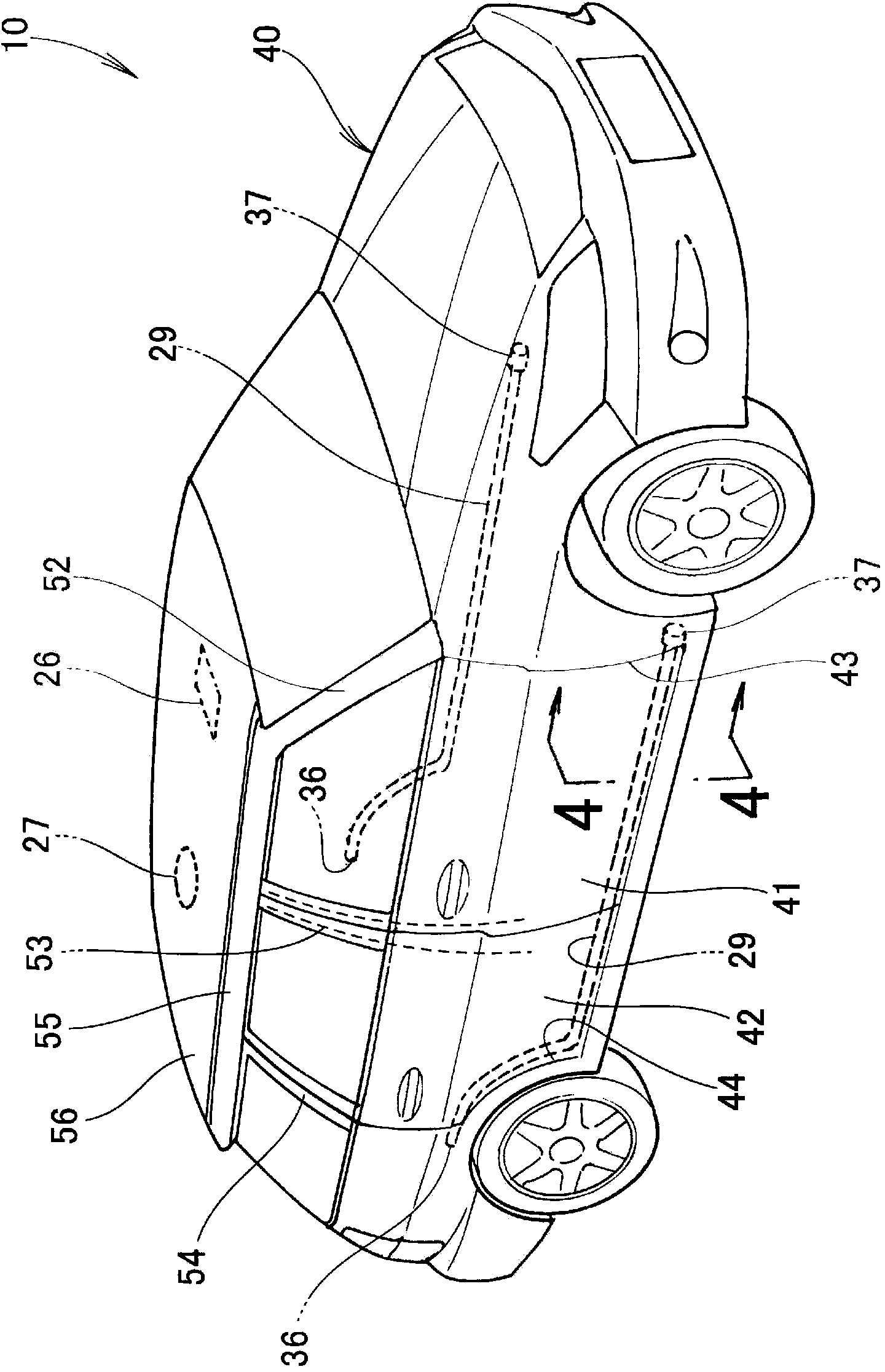
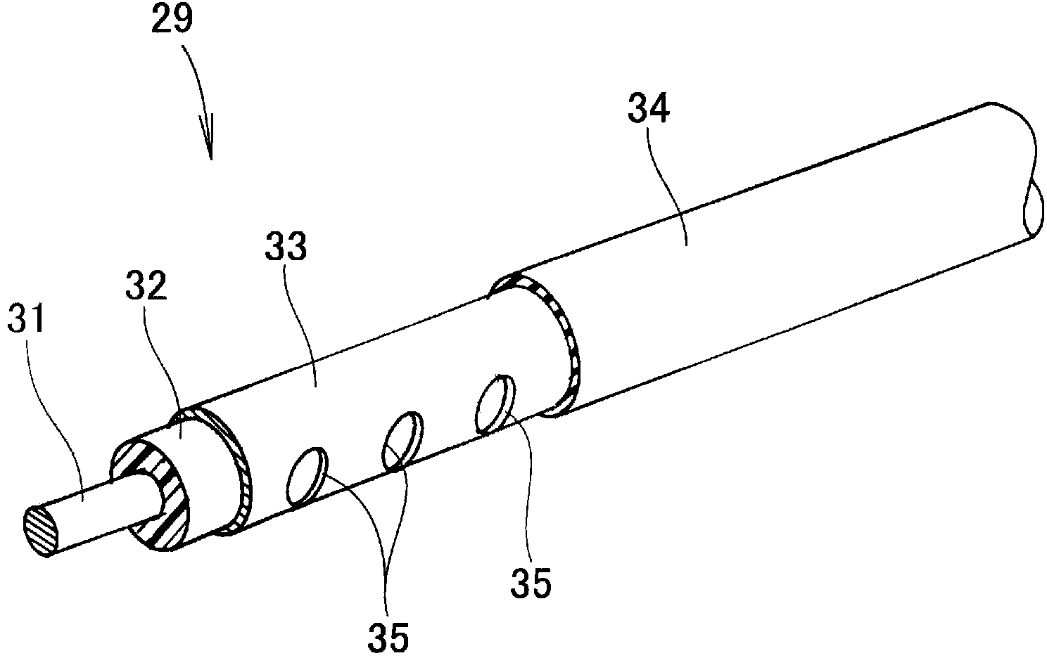
[0060] based on Figure 1 to Figure 9 The antenna arrangement structure of the vehicle communication device according to the first embodiment will be described. Such as figure 1 As shown, the vehicle communication device 21 is mounted on the vehicle 10 . The vehicle communication device 21 is capable of wireless communication with the mobile terminal 22 . The vehicle communication device 21 and the mobile terminal 22 constitute, for example, a vehicle electronic key system 20 . The vehicle electronic key system 20 is a system for locking and unlocking the doors 41, 41, 42, 42 of the vehicle 10 through wireless communication using the mobile terminal 22 without using a mechanical key, and is generally referred to as It is called a smart entry system.

[0061] The mobile terminal 22 is a type of a so-called key fob with an authentication function incorporated therein, and includes a mobile phone terminal and a high-function mobile phone terminal (smart phone). The mobile te...

Embodiment 2

[0126] based on Figure 10 as well as Figure 11 The antenna arrangement structure of the vehicle communication device according to the second embodiment will be described. Figure 10 with the above Figure 4 Express accordingly. The vehicle communication device 21A of the second embodiment is characterized in that the above-mentioned Figure 1 to Figure 9 The arrangement structure of the left and right indoor antennas 29, 29 (the left and right leaky coaxial cables 29, 29) of the shown embodiment 1 is changed to Figure 10 as well as Figure 11 configuration configuration shown, other configurations are the same as above Figure 1 to Figure 9 The example 1 shown is the same, and therefore description thereof will be omitted.

[0127] Next, the arrangement structure of the right indoor antenna 29 (right leaky coaxial cable 29) will be described. The arrangement structure of the left indoor antenna 29 (left leaky coaxial cable 29 ) is the same as the arrangement structur...

Embodiment 3

[0134] based on Figure 12 to Figure 14 The antenna arrangement structure of the vehicle communication device according to the third embodiment will be described. Figure 12 with the above Figure 4 Express accordingly. The vehicle communication device 21B of the third embodiment is characterized in that the above-mentioned Figure 1 to Figure 9 The arrangement structure of the left and right indoor antennas 29 and 29 of the shown embodiment 1 is changed to Figure 12 to Figure 14 configuration shown, for other configurations, with the above Figure 1 to Figure 9 The example 1 shown is the same, and therefore description thereof will be omitted.

[0135] Next, the arrangement structure of the right indoor antenna 29 (right leaky coaxial cable 29) will be described. The arrangement structure of the left indoor antenna 29 (left leaky coaxial cable 29 ) is the same as the arrangement structure of the right indoor antenna 29 except that it is left-right symmetrical, and there...


PUM


Abstract

An interior antenna (29, 29) of a vehicle communication apparatus (21) for performing wireless communication with a portable terminal device (22) present inside a cabin (11) is disposed in the cabin. The interior antenna includes left and right leaky coaxial cables that can transmit high-frequency band radio waves into the cabin. The left and right leaky coaxial cables are positioned under the cabin and inside left and right door inner panels (72) in a vehicle width direction, either above left and right side sills (51) or at end portions in the vehicle width direction above a floor panel (57), and extend in a vehicle front-rear direction.

Description

technical field [0001] The present invention relates to a communication device for a vehicle in which an antenna for performing wireless communication with a mobile terminal existing in the vehicle interior is arranged in the vehicle interior. In particular, the present invention relates to an antenna arrangement structure capable of suppressing leakage of radio waves in a high-frequency band transmitted from the antenna from the vehicle interior to the outside of the vehicle. In the present invention, the high frequency band refers to a frequency of at least 150 MHz. Background technique [0002] As the wireless communication system built in a vehicle, there is a system in which an antenna for wireless communication with a mobile terminal is disposed in the vehicle interior, such as a vehicle electronic key system. The vehicle electronic key system does not use a mechanical key, but locks and unlocks vehicle doors through wireless communication using a mobile electronic ke...

Claims


Application Information

Patent Timeline
Patent Type & Authority Applications(China)
IPC IPC(8): H01Q13/22H01Q1/22
CPCH01Q13/203H01Q1/3241H01Q1/3291H01Q13/20H01Q1/3283
Inventor 广濑素久
Owner HONDA MOTOR CO LTD
Why Eureka
Try Eureka