Spiral stirrer
A helical and helical technology, applied in mixers with rotating stirring devices, chemical/physical/physical-chemical stationary reactors, dissolution, etc., which can solve the problems of insufficient stirring, single U-shaped stirring blade turbine, and complicated equipment welding. and other problems, to achieve the effect of convenient installation and maintenance
Inactive Publication Date: 2015-02-25
SUZHOU HUARI JINLING MACHINERY
View PDF2 Cites 1 Cited by
- Summary
- Abstract
- Description
- Claims
- Application Information
AI Technical Summary
Problems solved by technology
Method used
View moreImage
Smart ImageViewing Examples

Examples
Embodiment Construction
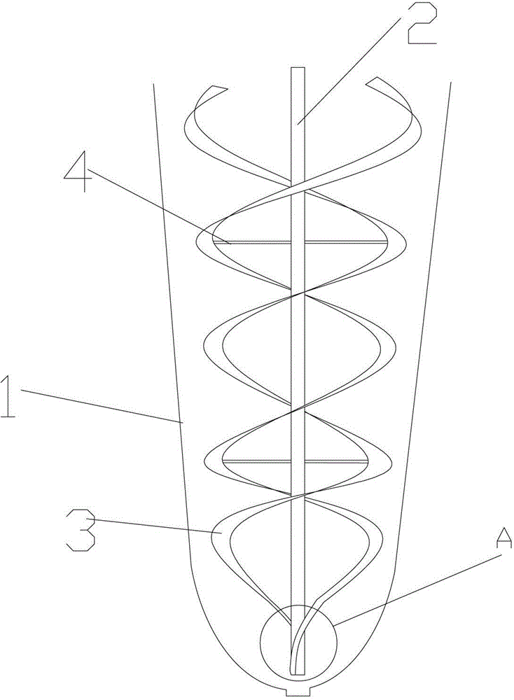
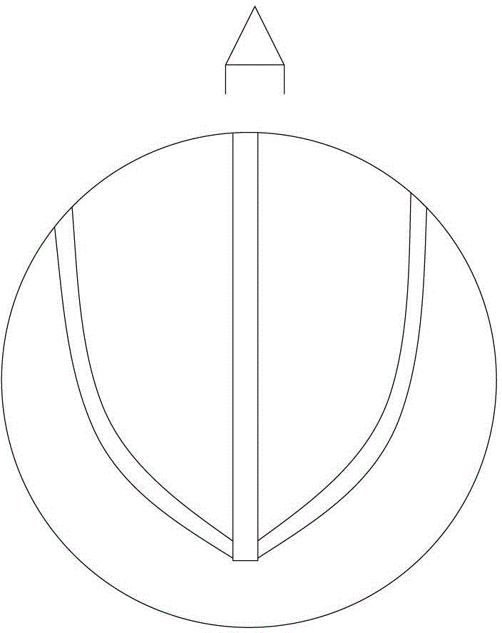
[0012] As shown in the figure, the spiral stirring includes a reaction tank 1, a rotating shaft 2, a stirring rod 3 and a support 4. The reaction tank is placed vertically, and the rotating shaft is vertically set at the center of the reaction tank and powered by a motor. The stirring rod is in a double helix structure around the rotating shaft. Setting, the bottom of the stirring rod is U-shaped, and the structure can be designed with the bottom shape of the reaction tank. The bottom of the stirring rod is fixedly connected with the bottom of the rotating shaft. The stirring rod is a segmented structure, and the spiral part is 3 sections. There are 3 supports.
Login to View More PUM
 Abstract
The invention discloses a spiral stirrer. The stirrer comprises a reaction tank, a rotation shaft, stirring rods, and a support; wherein the reaction tank is vertically arranged, the rotation shaft is vertically arranged on the center position of the reaction tank, the stirring rods are arranged in a double helix composition around the rotation shaft, the bottoms of the stirring rods are arranged in a U-shaped array and fixedly connected to the bottom of the rotation shaft, and the support fixes the stirring rods and the rotation shaft together. The provided spiral stirrer can fully stir substances in the reaction tank, and the sectional composition of the spiral stirrer is benefit for the installation and maintenance.
Description
technical field [0001] The invention relates to a spiral stirring. Background technique [0002] The stirring devices in the reaction equipment currently on the market are all single U-shaped stirring or impeller turbines. The welding of such equipment is complicated, and the internal stirring is not sufficient. Contents of the invention [0003] The invention aims at the deficiencies of the prior art, and provides a spiral type agitator with sufficient agitation, convenient disassembly and simple maintenance. [0004] The present invention realizes by following scheme: [0005] A spiral stirring, including a reaction tank, a rotating shaft, a stirring rod and a support, the reaction tank is vertically arranged, the rotating shaft is vertically arranged at the center of the reaction tank, the stirring rod is arranged in a double helix structure around the rotating shaft, and the bottom of the stirring rod is U-shaped For setting, the bottom of the stirring rod is fixedly...
Claims
Login to View More Application Information
Patent Timeline
 IPC IPC(8): B01J19/18B01F7/24
CPCB01J19/20B01J19/0066B01J19/18B01J2219/185
Inventor 向延海
Owner SUZHOU HUARI JINLING MACHINERY