Road cone put-away and release device of automatic traffic cone put-away and release trolley

A technology of automatic retractable and retractable devices, applied in traffic signals, roads, roads, etc., can solve the problems of no retractable accessories and achieve high retractable efficiency

Active Publication Date: 2015-02-25
HENAN GAOYUAN ROAD MAINTENANCE EQUIP
View PDF12 Cites 3 Cited by
  • Summary
  • Abstract
  • Description
  • Claims
  • Application Information

AI Technical Summary

Problems solved by technology

[0007] In order to solve the above-mentioned technical problems, the inventor of the present invention has invented the automatic retractable vehicle of traffic cones, which needs to solve a technical problem urgently at present. For this reason, the inventor of the present invention has invented the automatic retractable vehicle of traffic cones, but there is no corresponding There is an urgent need to develop a retractable device suitable for this car.

Method used


Image

  • Road cone put-away and release device of automatic traffic cone put-away and release trolley
  • Road cone put-away and release device of automatic traffic cone put-away and release trolley
  • Road cone put-away and release device of automatic traffic cone put-away and release trolley

Examples


Embodiment 1

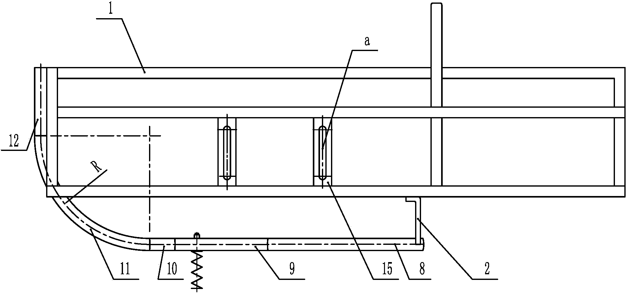
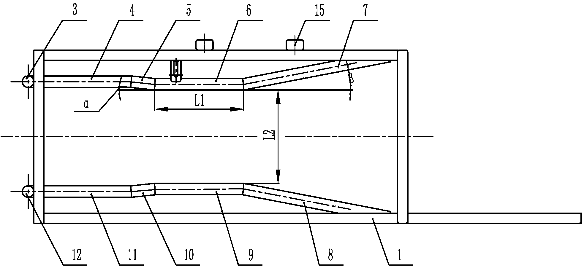
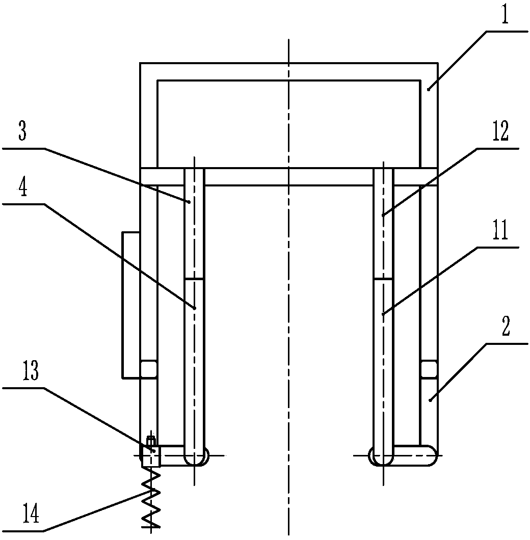
[0022] exist figure 1 , 2 , 3, the road cone retractable device of the traffic cone automatic retractable car of the present embodiment consists of a retractable frame support frame 1, a connecting plate 2, a rear vertical connection pipe 3, a rear righting pipe 4, a rear righting transition pipe 5, Rear correction pipe 6, rear storage pipe 7, front storage pipe 8, front correction pipe 9, front centering transition pipe 10, front centering pipe 11, front vertical connecting pipe 12, setting seat 13, setting rod 14, middle reinforcing plate 15 connections constitute.

[0023] The geometric shape of the retractable frame support frame 1 is a rectangular parallelepiped frame structure, and a rear vertical connecting pipe 3 is welded on the left rear end of the retractable frame support frame 1, and a rear centralizing pipe 4 is welded at the bottom end of the rear vertical connecting pipe 3 , the rear centralizing pipe 4 is an arc-shaped elbow, the central angle of the arc is ...

Embodiment 2

[0026]The rear vertical connection pipe 3 is welded on the left rear end of the retractable frame support frame 1 of this embodiment, and the rear vertical connection pipe 3 is welded with a rear centralizing pipe 4 at the bottom end of the rear vertical connecting pipe 3, and the rear centralizing pipe 4 is an arc-shaped elbow , the central angle of the arc is 80°, the arc radius R is 250mm, the other end of the rear centralizing pipe 4 is welded with a rear centralizing transition pipe 5, and the center line of the rear centralizing transition pipe 5 is connected to the bottom surface of the retractable frame support frame 1 The included angle ɑ between the center lines is 3°, and the other end of the transition pipe 5 is welded with a rear rectification pipe 6, the center line of the rear rectification pipe 6 is parallel to the center line of the bottom surface of the retractable frame support frame 1, and the rear rectification pipe 6 The length L1 is 200 mm. The other end...

Embodiment 3

[0028] The rear vertical connection pipe 3 is welded on the left rear end of the retractable frame support frame 1 of this embodiment, and the rear vertical connection pipe 3 is welded with a rear centralizing pipe 4 at the bottom end of the rear vertical connecting pipe 3, and the rear centralizing pipe 4 is an arc-shaped elbow , the central angle of the arc is 120°, the arc radius R is 380mm, the other end of the rear centralizing pipe 4 is welded with a rear centralizing transition pipe 5, and the center line of the rear centralizing transition pipe 5 is connected to the bottom surface of the retractable frame support frame 1 The included angle ɑ of the center line is 15°, the other end of the rear righting transition pipe 5 is welded with a rear correction pipe 6, the center line of the rear correction pipe 6 is parallel to the center line of the bottom surface of the retractable frame support frame 1, and the rear correction pipe 6 The length L1 is 400mm, the other end of ...


PUM

PropertyMeasurementUnit
Central angleaaaaaaaaaa
Arc radius raaaaaaaaaa

Abstract

Provided is a road cone put-away and release device of an automatic traffic cone put-away and release trolley. A rear vertical connecting pipe is arranged at the rear end of the left side of a put-away and release rack supporting frame, a rear straightening pipe is arranged at the bottom end of the rear vertical connecting pipe, a rear straightening transition pipe is arranged at the tail end of the rear straightening pipe, a rear correcting pipe is arranged at the tail end of the rear straightening transition pipe, a storage pipe is arranged at the tail end of the rear correcting pipe, a shifting and correcting base is arranged on the outer side of the rear correcting pipe, a shifting and correcting rod is arranged on the shifting and correcting base, a connecting plate is arranged between the rear storage pipe and the put-away and release rack supporting frame as well as between a front storage pipe and the put-away and release rack supporting frame, a front vertical connecting pipe, a front straightening pipe, a front correcting pipe and the front storage pipe symmetrical with the rear vertical connecting pipe, the rear straightening pipe, the rear correcting pipe and the rear storage pipe about the central plane in the length direction are arranged at the front end of the left side of the put-away and release rack supporting frame and the bottom of the put-away and release rack supporting frame, and a through groove a is machined in a reinforcing plate in the middle of the side face of the put-away and release rack supporting frame. Through the device, traffic cones inverted on a road surface can be straightened to stand on the road surface, and the traffic cones on the road surface can be pushed to a mechanical arm to be put back to the automatic traffic cone put-away and release trolley.

Description

technical field [0001] The invention belongs to the technical field of equipment or devices for repairing or rehabilitating completed road surfaces, and in particular relates to the placement and recovery of traffic cone equipment components on the road surface. Background technique [0002] At present, during maintenance work on expressways in my country, the placement and recovery of traffic cones are carried out by 2 to 3 construction workers at the rear of the road engineering vehicle along the specific route of the expressway. This manual operation method, The operation speed is slow, the safety factor is low, and the spacing of traffic cones is not uniform, especially when working on express roads in cities with heavy traffic flow. Or the risk factor is higher in severe environments such as thunderstorms. [0003] In recent years, although some units have begun to focus on the research of automatic retractable devices for traffic cones, the technology is still immature,...

Claims


Application Information

Patent Timeline
IPC IPC(8): E01F9/014E01F9/70
Inventor 薛韶华王士乐陈在旭刘廷国
Owner HENAN GAOYUAN ROAD MAINTENANCE EQUIP
Why Eureka
Try Eureka