
Cast-in-place pile structure

A technology of cast-in-place piles and bored piles, which is applied in foundation structure engineering, sheet pile walls, buildings, etc., can solve problems such as accidents, high costs, and influence on construction progress, and achieve strong bearing capacity, high pull-out strength, and piling convenient effect

Active Publication Date: 2015-02-25
浙江原野建设有限公司
View PDF7 Cites 1 Cited by
  • Summary
  • Abstract
  • Description
  • Claims
  • Application Information

AI Technical Summary

Problems solved by technology

It is very difficult to carry out pile foundation construction in karst areas, with many accidents, slow progress and high cost, especially in the strata where karst caves are encountered, problems such as slurry leakage, broken piles, and karst cave collapse are prone to occur
In recent years, with the widespread application of mechanically drilled cast-in-place piles and self-reflexive force balance load boxes, when a large number of mechanically drilled cast-in-situ piles are constructed, tapers caused by construction machinery drill bits will appear at the bottom. During the placement of the pile, the lowermost reinforced cast-in-situ pile is inserted into the taper hole, causing the steel bars of the entire pile body to tilt with the load box, which may cause unnecessary accidents and affect the construction progress

Method used


Image

  • Cast-in-place pile structure

Examples


Embodiment Construction

[0014] The present invention is described in further detail now in conjunction with accompanying drawing. These drawings are all simplified schematic diagrams, which only illustrate the basic structure of the present invention in a schematic manner, so they only show the configurations related to the present invention.

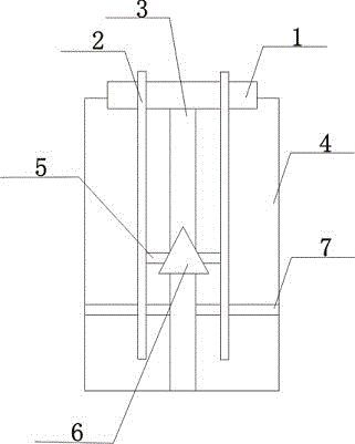
[0015] Such as figure 1 The preferred embodiment of the cast-in-situ pile structure of the present invention shown includes an anchor plate 1, and an annular plate 4 is arranged on both sides of the anchor plate 1. The annular plate 4 is formed by splicing two plates, and the gap between the annular plate 4 and the anchor plate 1 is Connected by pins, the annular plate 4 is provided with bored cast-in-place piles 2, and there are two bored cast-in-place piles 2, and the bored cast-in-place piles 2 are vertically arranged on the anchor plate 1, and the tops of the bored cast-in-place piles 2 extend on the anchor plate 1. Outside the upper surface of the plate ...


PUM


Abstract

The invention discloses a cast-in-place pile structure. The cast-in-place pile structure comprises an anchor plate. Annular plates are arranged on the two sides of the anchor plate, the annular plates are formed by splicing two plate bodies, and the annular plates and the anchor plate are connected through pin shafts. The annular plates are provided with cast-in-situ bored piles, the number of the cast-in-situ bored piles is two, and the cast-in-situ bored piles are vertically arranged on the anchor plate. The top ends of the cast-in-situ bored piles extend to the outer side of the upper surface of the anchor plate, and the bottoms of the cast-in-situ bored piles penetrate through a pre-stressed anchor cable to extend to the outer side of the lower surface of the pre-stressed anchor cable. A main reinforcement bar is arranged between the two cast-in-situ bored piles, and the two ends of the main reinforcement bar are fixed on the cast-in-situ bored piles. A bag is further included, the top of the bag is placed on the lower surface of the anchor plate, and the bottom of the bag is placed on the inner bottom faces of the annular plates. A reinforcing plate is arranged at the connecting position of the bag and the main reinforcement bar. The cast-in-place pile structure is high in single-pile bearing capacity, high in pulling resistance, capable of enabling cast-in-place piles to be kept at the centers of pile holes as far as possible in the burying process, capable of avoiding excessive rod moving data, easy to construct, capable of driving piles into the earth conveniently, sturdy and durable, and capable of effectively achieving a reinforcement effect.

Description

technical field [0001] The invention relates to a building facility, in particular to a cast-in-place pile structure. Background technique [0002] my country has a vast territory, complex and diverse geological conditions, and karst areas are distributed in many areas. It is very difficult to carry out pile foundation construction in karst areas, with many accidents, slow progress, and high cost. Especially in the stratum where karst caves are encountered, problems such as slurry leakage, broken piles, and karst cave collapse are prone to occur. In recent years, with the widespread application of mechanically drilled cast-in-place piles and self-reflexive force balance load boxes, when a large number of mechanically drilled cast-in-situ piles are constructed, tapers caused by construction machinery drill bits will appear at the bottom. During the placement of the pile, the lowermost reinforced cast-in-situ pile was inserted into the taper hole, causing the steel bars of th...

Claims


Application Information

Patent Timeline
IPC IPC(8): E02D5/34
CPCE02D5/34E02D5/58E02D2250/0046E02D2300/002
Inventor 文国栋
Owner 浙江原野建设有限公司
Learn More