Hydraulic oil tank

A technology of hydraulic oil tank and oil tank, which is applied in the direction of oil supply tank device, fluid pressure actuating device, fluid pressure actuating system components, etc. Cavity and other problems to achieve the effect of improving reliability and stability, facilitating thorough cleaning and improving cleanliness

Inactive Publication Date: 2015-02-25
CHANGZHOU WEIMATAI PRECISION TOOLS
View PDF0 Cites 35 Cited by
  • Summary
  • Abstract
  • Description
  • Claims
  • Application Information

AI Technical Summary

Problems solved by technology

However, the existing hydraulic oil will cause granular impurities during use, and these impurities will cause wear on the relative moving surface of the hydraulic components, blockage of the nozzle, and greatly reduce the reliability of the system. Although the bottom of the traditional hydraulic oil tank is equipped with Oil drain port, but the oil drain port has no cavity, so impurities will flow with the hydraulic oil, affecting the normal operation of the entire hydraulic system

Method used


Image

  • Hydraulic oil tank
  • Hydraulic oil tank

Examples


Embodiment Construction

[0014] The present invention will be further described below in conjunction with the accompanying drawings and specific embodiments.

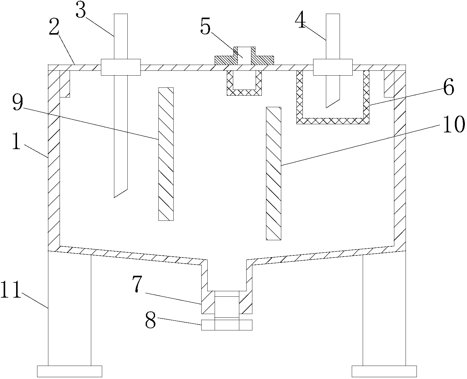
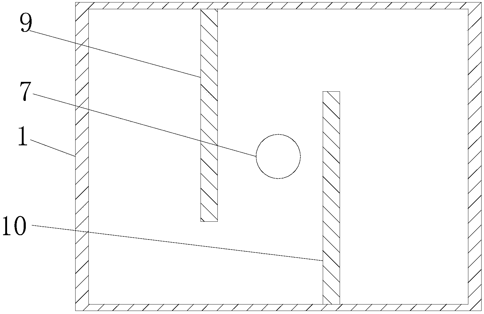
[0015] Such as figure 1 with figure 2 , a hydraulic oil tank, including a fuel tank 1, the fuel tank 1 is provided with a cover plate 2, the cover plate 2 is provided with an oil suction pipe 3, an oil return pipe 4 and a fuel pipe 5, and the inner wall of the cover plate 2 is provided with a filter screen 6, which is located in the fuel tank The mouth of the oil return pipe 4 in 1 is set in the filter screen 6, the bottom of the oil tank 1 is provided with a sedimentation tank 7, the upper end surface of the sedimentation tank 7 is lower than the bottom surface of the oil tank, and the lower end surface of the sedimentation tank 7 is provided with a closing plug 8, said The fuel tank 1 is provided with a first partition 9 and a second partition 10 fixed on the inner wall of the fuel tank 1 .

[0016] The closure plug 8 is made of magnetic m...


PUM


Abstract

The invention relates to a hydraulic oil tank. The hydraulic oil tank comprises an oil tank body. A cover plate is arranged on the oil tank body. An oil suction pipe, an oil return pipe and an oil filling pipe are arranged on the cover plate, a filter screen is arranged on the inner wall of the cover plate, and the opening, located inside the oil tank body, of the oil return pipe is formed in the filter screen. A precipitation tank is arranged at the bottom of the oil tank body, the upper end face of the precipitation tank is lower than the bottom surface of the oil tank body, and a closing plug is arranged on the lower end face of the precipitation tank. A first partition plate and a second partition plate are arranged in the oil tank body and fixed to the inner wall of the oil tank body. The hydraulic oil tank has the advantages of being good in filtering effect, capable of effectively discharging impurities in hydraulic oil and preventing the impurities from flowing in the hydraulic oil and the like.

Description

technical field [0001] The invention relates to the technical field of oil tanks, in particular to hydraulic oil tanks. Background technique [0002] Effectively controlling the intrusion of pollutants and the generation of pollutants in the hydraulic system is the key to improving the life of the hydraulic system. However, the existing hydraulic oil will cause granular impurities during use, and these impurities will cause wear on the relative moving surface of the hydraulic components, blockage of the nozzle, and greatly reduce the reliability of the system. Although the bottom of the traditional hydraulic oil tank is equipped with There is an oil drain port, but the oil drain port has no cavity, so impurities will flow with the hydraulic oil, affecting the normal operation of the entire hydraulic system. Contents of the invention [0003] In view of the above problems, the object of the present invention is to provide a hydraulic oil tank with good filtering effect, wh...

Claims


Application Information

Patent Timeline
Patent Type & Authority Applications(China)
IPC IPC(8): F15B1/26F15B21/04
CPCF15B1/26F15B21/041F15B21/042
Inventor 毕平艳
Owner CHANGZHOU WEIMATAI PRECISION TOOLS
Why Eureka
Try Eureka