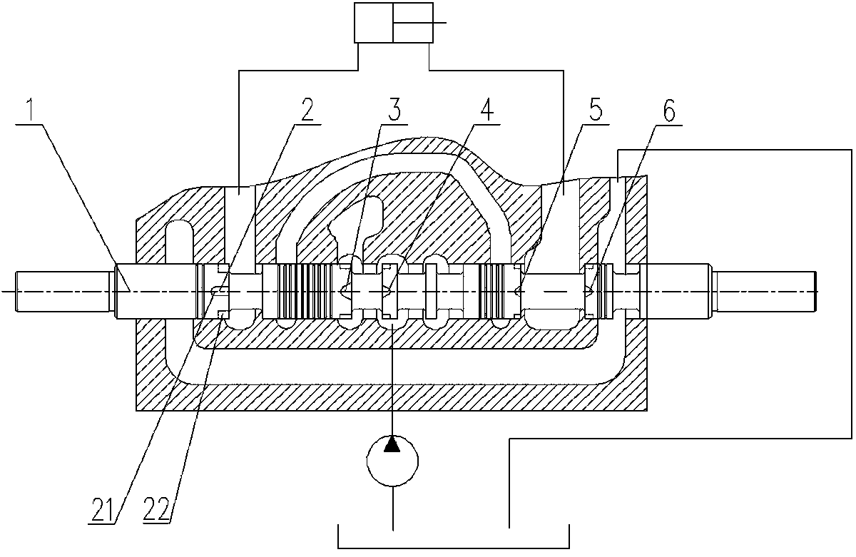
Valve element of hydraulic multi-way valve

A multi-way valve and spool technology, applied in the direction of valve details, valve devices, fluid pressure actuators, etc., can solve the problems of reduced work efficiency, difficulty in speed regulation range and precise control of working devices, etc., to improve precise positioning, The effect of avoiding shock phenomenon and smooth motion, improving micromanipulation performance and precise positioning

Active Publication Date: 2015-02-25
LIUGONG CHANGZHOU MACHINERY
View PDF7 Cites 6 Cited by
  • Summary
  • Abstract
  • Description
  • Claims
  • Application Information

AI Technical Summary

Problems solved by technology

Too small speed range makes it difficult for the operator to accurately co

Method used


Image

  • Valve element of hydraulic multi-way valve
  • Valve element of hydraulic multi-way valve
  • Valve element of hydraulic multi-way valve

Examples


Example Embodiment

[0022] Example one

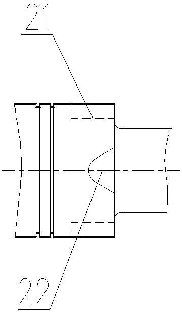
[0023] Such as figure 2 As shown, the auxiliary throttle groove 22 is a triangular throttle groove, and the inner top adopts a circular arc transition.

Example Embodiment

[0024] Example two

[0025] Such as image 3 As shown, the auxiliary throttle groove 22 is formed by superimposing two semicircular throttle grooves.

Example Embodiment

[0026] Example three

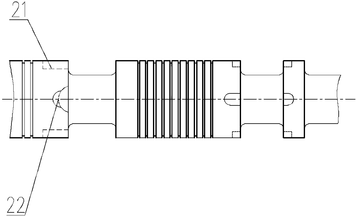
[0027] Such as Figure 4 As shown, the auxiliary throttle groove 22 is an elongated groove with a semicircular inner end, and the depth of the elongated groove gradually increases. The auxiliary throttle groove 22 can also be directly a semicircular throttle groove.

[0028] Through simulation calculation and actual test verification, the present invention sets multiple combinations of basic throttle groove 21 and auxiliary throttle groove 22 on the multi-way valve spool body 1, and passes the auxiliary throttle with different throttle area and different throttle length. The groove 22 is combined to achieve a change in the flow area of ​​the spool proportional to the displacement of the spool, thereby adjusting the flow and pressure entering the valve port, improving the micro-motion performance of the loader's working device and the precise positioning of the working device.

[0029] The present invention only needs to be installed on the first throttle groo...


PUM


Abstract

A valve element of a hydraulic multi-way valve comprises a valve element body, and the valve element body is provided with a first throttling groove set, a second throttling groove set, a third throttling groove set, a fourth throttling groove set and a fifth throttling groove set. The throttling groove sets of different shapes and different opening lengths are formed in the valve element body so that the flow of the valve element can be directly proportional to the whole process of valve element displacement; the impact phenomenon generated in the opening and closing process of the valve element can be effectively avoided, motion stationarity can be effectively achieved, and therefore microoperation performance and precise location of lifting or descending of a working device of a loader are improved.

Description

technical field [0001] The invention relates to a core component of a hydraulic multi-way valve, in particular to a hydraulic multi-way valve spool applied to engineering machinery such as loaders, and belongs to the technical field of engineering machinery. Background technique [0002] A loader is a kind of construction machinery mainly for loading and unloading materials. It is mainly used to load materials and transfer materials in a short distance. After unloading, it returns to the original place for loading. When the loader uses a fork to load and transport goods, it is necessary to fine-tune the loader's working device when placing the goods in order to adjust the height of the goods. Therefore, a loader that uses a fork to load and transport goods has higher requirements on the fine-tuning performance of the multi-way valve spool. In order to improve work efficiency, the operator often needs to quickly push the joystick so that the working device can be quickly lif...

Claims


Application Information

Patent Timeline
IPC IPC(8): F15B13/02
CPCF15B13/022F16K47/04
Inventor 牛宏杰马志刚王展
Owner LIUGONG CHANGZHOU MACHINERY
Why Eureka
Try Eureka