Mechanical self-locking oil cylinder

A self-locking and self-locking technology, applied in the direction of fluid pressure actuating devices, etc., can solve the problems of unreliable pressure-holding self-locking oil cylinders, inability to resist workpiece vibration, and inability to realize automaticity, etc., to achieve reliable self-locking functions and structural Compact, inexpensive to manufacture effect

Inactive Publication Date: 2015-02-25
吴贤卜
View PDF9 Cites 3 Cited by
  • Summary
  • Abstract
  • Description
  • Claims
  • Application Information

AI Technical Summary

Problems solved by technology

This pressure-maintaining self-locking oil cylinder is unreliable, because the oil pressure in the compression chamber changes with the change of the ambient temperature, there may be leakage in the compression chamber, the oil is compressible, and the compression force generated by the oil cylinder cannot resist the workpiece The vibration of the existing threaded self-locking oil cylinder is to add a section of thread and a nut to one end of the piston rod. When the oil cylinder presses the workpiece, the nut is tightened to fix the pressing position of the oil cylinder. This method cannot be realized automatically. Manual operation, low efficiency, relatively large human factors

Method used


Image

  • Mechanical self-locking oil cylinder
  • Mechanical self-locking oil cylinder
  • Mechanical self-locking oil cylinder

Examples


Embodiment Construction

[0021] The preferred embodiments of the present invention will be described below in conjunction with the accompanying drawings. It should be understood that the preferred embodiments described here are only used to illustrate and explain the present invention, and are not intended to limit the present invention.

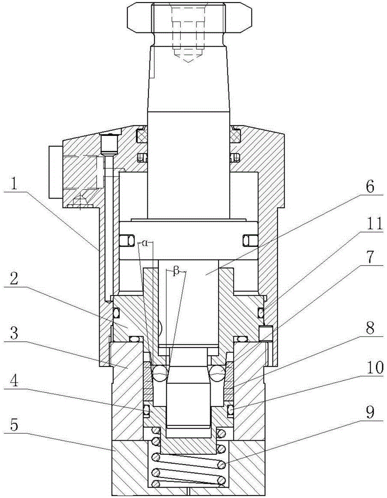
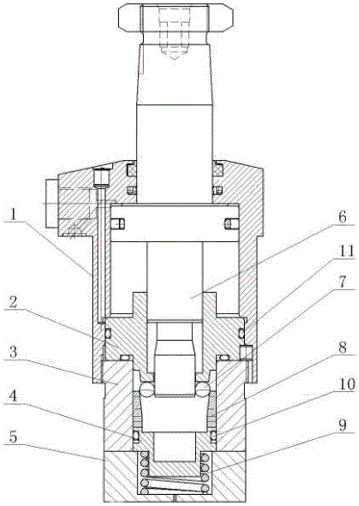
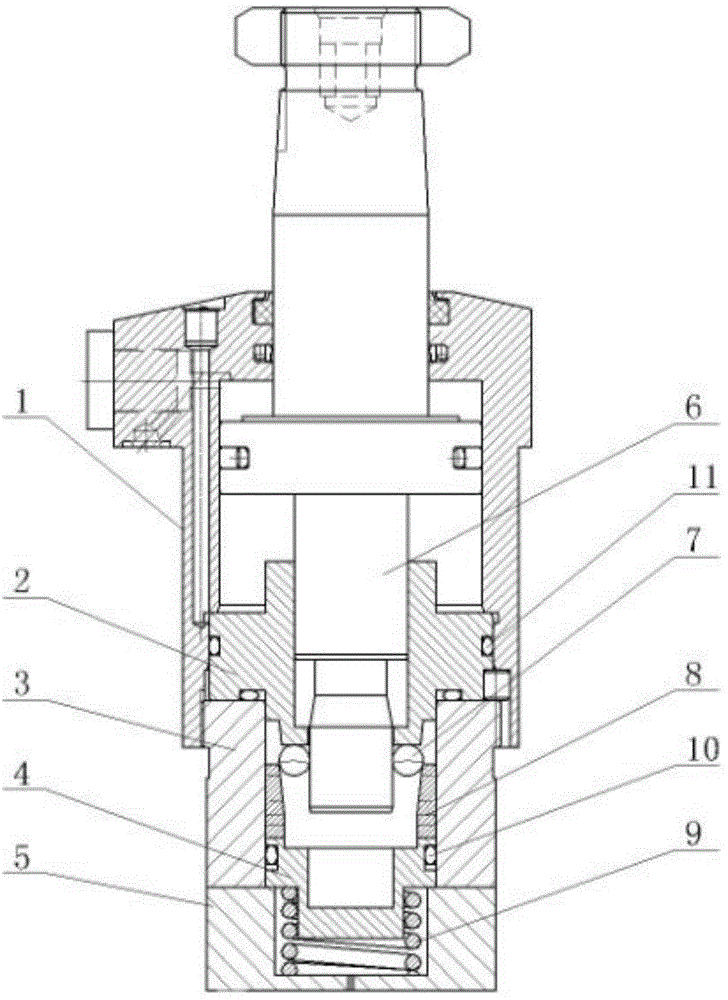
[0022] Such as Figure 1 to Figure 6 As shown, a mechanical self-locking oil cylinder includes a cylinder body 1, a piston rod 6 is installed on the inner side of the cylinder body 1, a self-locking cylinder 3 is installed on the bottom of the cylinder body 1, and a cover plate 5 is installed on the lower end of the self-locking cylinder 3, The inner side of the cover plate 5 is equipped with a self-locking spring 9, the lower end of the self-locking spring 9 is connected with the cover plate 5, the inner lower part of the self-locking cylinder 3 is installed with a self-locking piston 4, and the lower end of the self-locking piston 4 is connected with the self-locki...


PUM


Abstract

The invention discloses a mechanical self-locking oil cylinder which comprises a cylinder body. A piston rod is mounted in the cylinder body. A self-locking cylinder barrel is mounted on the lower portion of the cylinder body. A cover plate is mounted at the lower end of the self-locking cylinder. A self-locking spring is mounted on the inner side of the cover plate. The lower end of the self-locking spring is connected with the cover plate. A self-locking piston is mounted on the lower portion of the inner side of the self-locking cylinder barrel. The lower end of the self-locking piston is connected with a self-locking spring. A fixing seat is mounted on the lower portion of the cylinder body. The fixing seat is located on the upper side of the self-locking cylinder barrel. The lower end of the fixing seat is matched with the self-locking cylinder barrel. Multiple self-locking sheets are mounted on the inner side of the self-locking cylinder barrel and located between the fixing seat and the self-locking cylinder barrel. The upper portion of the piston rod is matched with the cylinder body. The middle portion of the piston rod is matched with the fixing seat. The lower end of the piston rod is matched with the self-locking piston. According to the mechanical self-locking oil cylinder, on the premise that the oil channels of the oil cylinder are not changed, automatic mechanical self locking of the oil cylinder is achieved, pressing force is generated on a workpiece, and the mechanical self-locking oil cylinder is compact in structure, small in size and reliable and stable in self-locking function.

Description

technical field [0001] The invention relates to an oil cylinder, more precisely a mechanical self-locking oil cylinder. Background technique [0002] The existing oil cylinder adopts a pressure-maintaining self-locking oil cylinder. This method is not strictly a mechanical self-locking. It is to maintain pressure in the compression chamber of the oil cylinder to fix the compression position of the piston rod. This pressure-maintaining self-locking oil cylinder is unreliable, because the oil pressure in the compression chamber changes with the change of the ambient temperature, there may be leakage in the compression chamber, the oil is compressible, and the compression force generated by the oil cylinder cannot resist the workpiece The vibration of the existing threaded self-locking oil cylinder is to add a section of thread and a nut to one end of the piston rod. When the oil cylinder presses the workpiece, the nut is tightened to fix the pressing position of the oil cylind...

Claims


Application Information

Patent Timeline
Patent Type & Authority Applications(China)
IPC IPC(8): F15B15/14F15B15/26
CPCF15B15/14F15B15/261
Inventor 吴贤卜徐安林甘辉
Owner 吴贤卜
Why Eureka
Try Eureka