

Blast hole explosion blocking method
A blasthole and orifice technology, which is applied in the field of open-air deep-hole step blasting and blockage construction of blasthole blasting, can solve problems such as rapid drop in detonation gas pressure, difficulty in ensuring blockage and compaction, and affect the safety of blasting operations. The effect of blasting effect, improving energy utilization rate, good practical effect and economic effect
Active Publication Date: 2015-02-25
CHINA GEZHOUBA GRP YIPULI CO LTD
View PDF4 Cites 13 Cited by
- Summary
- Abstract
- Description
- Claims
- Application Information
AI Technical Summary
Problems solved by technology
[0003] At present, the above-mentioned dense material B is mainly used for dense plugging in blasthole blasting, and the plugging length generally accounts for about 1/3 of the blasthole depth. Large, and the blocking operation usually adopts manual operation, which leads to a very high labor intensity for workers
In addition, due to the large length of the plugging, it is difficult to ensure the compactness of the plugging.
Method used
View moreImage
Smart ImageViewing Examples


Examples
 PUM
| Property | Measurement | Unit |
|---|---|---|
| Height | aaaaa | aaaaa |
| Diameter | aaaaa | aaaaa |
| Compaction density | aaaaa | aaaaa |
Abstract
The invention discloses a blast hole explosion blocking method. The method includes the following construction steps that a, buffering air bags are obtained and are each of a cylindrical structure; b, an explosive is arranged at the middle portion in a blast hole, so that an explosive containing section is formed, then the blast hole is blocked through drilling cuttings, and therefore a dense blocked section is formed; c, the buffering air bags obtained in the step a are sequentially placed in the blast hole, so that a buffering air bag set is formed; d, the step b and the step c are finished repeatedly, so that dense blocked sections and the buffering air bags are arranged alternately; e, the blast hole is blocked through the drilling cuttings, blockage work of the remaining portion of a hole opening is finished, and the last dense blocked section is formed. According to the construction method, due to the fact that the buffering air bag set occupies a large space, the use number of blocking materials is reduced, and labor intensity of workers is relieved; the acting time of explosion gas in the blast hole can be prolonged, so that the explosion crushing effect is improved, the blast hole is effectively prevented from being punched, and the explosion operation safety level is improved.
Description
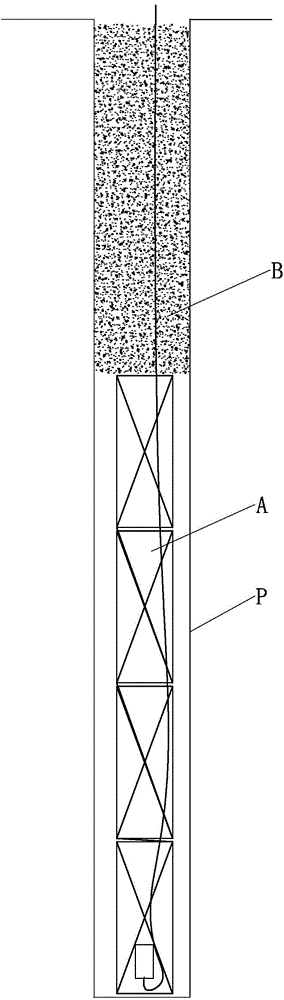
technical field [0001] The invention belongs to the technical field of engineering blasting, and relates to a plugging construction method for blasthole blasting. The construction method is especially suitable for open-air deep hole step blasting. Background technique [0002] Blast hole blasting method is the most common blasting construction method, the blast hole charge structure (such as figure 1 shown) is usually composed of a charge section A located in the middle and lower part of the blasthole P and a dense plugging section B located at the top of the blasthole, where the charge section is filled with explosives, and the plugging section is made of dense materials such as cuttings, mud, and crushed stones. Fill it tightly. After the explosive is detonated, it explodes in the blast hole to form a detonation wave. Under the joint action of the stress wave generated by the detonation wave and the expansion of the detonation gas, the blasting effect of crushing ore and ...
Claims
Login to View More Application Information
Patent Timeline
 IPC IPC(8): F42D1/18
Inventor周桂松
OwnerCHINA GEZHOUBA GRP YIPULI CO LTD