Wiring harness tensile force test clamp capable of being moved and adjusted in multiple directions

A tensile test and multi-directional technology, applied in tension measurement and other directions, can solve problems such as waste of resources, poor extensibility, and unusability, and achieve the effects of improving efficiency, good extensibility, and saving costs

Active Publication Date: 2015-02-25
HUIZHOU ZHUCHENG WIRING SYST
View PDF6 Cites 4 Cited by
  • Summary
  • Abstract
  • Description
  • Claims
  • Application Information

AI Technical Summary

Problems solved by technology

[0002] If the product needs to be launched on the market after design, or in the process of mass production, a series of product tests need to be carried out. The existing tensile test fixture is designed according to the needs of different products, resulting in the test fixture It can only be applied to specific products. When different products are replaced, it will lead to unusability, poor extensibility, waste of original resources, and increase the cost of fixture development for enterprises.

Method used


Image

  • Wiring harness tensile force test clamp capable of being moved and adjusted in multiple directions
  • Wiring harness tensile force test clamp capable of being moved and adjusted in multiple directions

Examples


Embodiment Construction

[0019] The content of the present invention will be further described in detail below in conjunction with the accompanying drawings and embodiments.

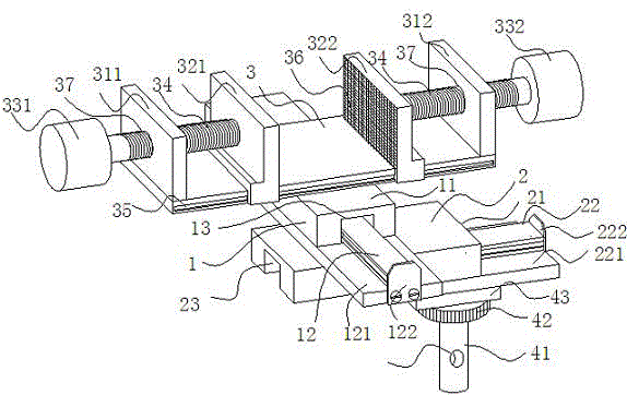
[0020] figure 1 It is a structural schematic diagram of the clamp embodiment of the present invention, such as figure 1 As shown, the test fixture includes a clamping part 3, a first sliding part 1, a second sliding part 1 and a mounting head 4. The clamping part 3 is arranged on the upper part of the first sliding part 1, and the first sliding part 1 and the second sliding part 1 are vertically connected and fixed, the sliding part can move and slide in a straight line, and cooperate with the second sliding part 1 to realize the multi-directional movement adjustment of the clip part 3.

[0021] The clamping part 3 includes a third slide rail 35, and the two ends of the third slide rail 35 are provided with fixed ends 311, 312, and also includes a first clamping end 321 and a second clamping end 322 sliding on the third slide r...


PUM


Abstract

The invention discloses a wiring harness tensile force test clamp capable of being moved and adjusted in multiple directions. The clamp comprises two sliding portions, a clamping portion and a mounting head. The two sliding portions can achieve linear sliding and comprise a first sliding portion and a second sliding portion; the first sliding portion and the second sliding portion each comprise a first positioning portion, a second positioning, a first sliding groove, a second sliding groove, a first sliding rail and a second sliding rail; each first sliding groove and each second sliding groove are formed in the lower portions of the corresponding positioning portions; each first sliding rail and each second sliding rail slide on the corresponding sliding grooves; the first sliding rail are perpendicularly connected and fixed with the upper portions of the second positioning portion; the clamping portion is used for clamping a wiring harness and is arranged on the first positioning portions of the first sliding portions; one end of the mounting head is connected with the second sliding portions, and the other end of the mounting head is provided with a fixed shaft for being fixed to the clamp. Through the two perpendicular guide rails, multi-direction moving of the clamping portion can be achieved, and therefore the clamping portion is not limited at a certain position, and adjustment is facilitated. The clamp can be applied to tests of different wiring harness products, cost of an enterprise for developing different testing clamps is greatly saved, and benefits of the enterprise are improved.

Description

technical field [0001] The invention relates to the field of test fixtures, in particular to a harness tension test fixture capable of multi-directional movement and adjustment. Background technique [0002] If the product needs to be launched on the market after design, or in the process of mass production, a series of product tests need to be carried out. The existing tensile test fixture is designed according to the needs of different products, resulting in the test fixture It can only be applied to a specific product. When a different product is replaced, it will be unusable, poor in extensibility, wasting original resources, and increasing the cost of fixture development for the enterprise. Contents of the invention [0003] In view of this, the problem to be solved by the present invention is to provide a wire harness tension test fixture that can be applied to different products and can be moved and adjusted in multiple directions. [0004] In order to solve the ab...

Claims


Application Information

Patent Timeline
Patent Type & Authority Applications(China)
IPC IPC(8): G01L5/04
Inventor 黄廷东
Owner HUIZHOU ZHUCHENG WIRING SYST
Why Eureka
Try Eureka