
Power converter for wind turbine with real-time power generation and full-time grid connection function

A power converter, real-time power generation technology, applied in wind power generation, electrical components, circuit devices, etc., can solve problems such as the benefits that are not in line with the application of wind resources and the weakening of wind power

Active Publication Date: 2018-03-06
东元总合科技(杭州)有限公司
View PDF3 Cites 0 Cited by
  • Summary
  • Abstract
  • Description
  • Claims
  • Application Information

AI Technical Summary

Problems solved by technology

Or use the energy of the battery device to supply power to the subsequent circuit. The battery device is charged by the mains network through a bidirectional converter, and then supplies power to the AC load through the bidirectional converter. It can be applied to uninterruptible power systems and solar energy converter architectures , this type of wind power converter will shut down when there is no wind. When the wind starts to drive the generator, the generator must generate AC power higher than a certain voltage level and then rectify it into DC power to drive this type of power converter. , after driving the power converter, it is necessary to wait for a period of time for the power converter to be connected to the grid before the electric energy generated by the fan can be sent to the grid; Weaken the shutdown of the wind turbine. When the wind turbine is shut down, the power converter is bound to enter the shutdown state again and wait for the next wind blowing; from the perspective of wind resource application, this type of power converter cannot maximize the energy generated by the wind turbine. In the long run, it is not in line with the benefits of wind resources application

Method used


Image

  • Power converter for wind turbine with real-time power generation and full-time grid connection function

Examples


Embodiment Construction

[0017] The present invention will be further described below in conjunction with accompanying drawing.

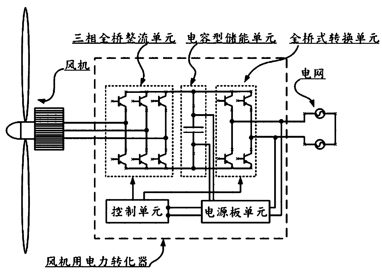
[0018] The power converter for wind turbine with real-time power generation and full-time grid connection function of the present invention has the full-time grid connection function, which is further explained as the power converter proposed by the present invention is connected to the power grid all-weather, unless the fan fails or power grid failure and other unpredictable external force factors, otherwise the power converter of the present invention will not shut down; when the wind power generator (referred to as the fan) drives the blades to generate kinetic energy due to wind force, and the kinetic energy of the blades drives the generator to generate electricity, the power converter will turn the fan The generated electric energy is transmitted to the grid, and the wind turbine is electrically connected to the power converter.

[0019] Such as figure 1 As shown, th...


PUM


Abstract

The invention discloses a draught fan electric power converter with the real-time electricity generating and full-time grid connecting functions. The draught fan electric power converter comprises a draught fan electric power converter body. The electric power converter body is electrically connected with a draught fan and a power grid connected with the electric power converter body in a lapped mode, and the electric power converter body is connected with the power grid in parallel all the time. After the draught fan rotates windward and generates power, the energy produced by the draught fan can be converted into alternating voltage with the level same as the voltage of the power grid through the draught fan electric power converter body, and the produced energy is transmitted to the power grid through the alternating voltage output through the electric power converter body. The draught fan electric power converter body is connected with the power grid in parallel in the lapped mode all the day, the electric energy produced by the draught fan can be converted by the electric power converter body in real time and transmitted to the power grid.

Description

technical field [0001] The invention relates to a power converter for a fan, in particular to a power converter for a fan with the functions of real-time power generation and full-time grid connection. Background technique [0002] In response to concepts such as environmental protection and energy saving, renewable energy is widely and widely used all over the world. Since renewable energy is not as capable of outputting a large amount of stable and usable energy as thermal power and nuclear energy, climate accounts for a large part of the factor when using renewable energy. For example, solar resources have cloudy and sunny days, high or low temperature, etc., which will affect the power generation efficiency, while wind resources have uncertain factors such as strong and weak winds and turbulent winds. Therefore, the converters used in renewable energy must have special mechanisms in order to be used efficiently. Unstable renewable energy. [0003] Due to the highly unst...

Claims


Application Information

Patent Timeline
Patent Type & Authority Patents(China)
IPC IPC(8): H02J3/38
CPCH02J3/386Y02E10/76
Inventor 申林刘书芳刘魏
Owner 东元总合科技(杭州)有限公司
Learn More