Frequency sweeping signal generating circuit

A technique for sweeping frequency signals and generating circuits, which is applied in the microwave field and can solve the problems of not being able to realize fast frequency sweeping at the same time, and not being able to expand the sweeping range at the same time, and the spectral purity of the sweeping signal.

Inactive Publication Date: 2015-02-25
NUCTECH CO LTD
View PDF9 Cites 4 Cited by
  • Summary
  • Abstract
  • Description
  • Claims
  • Application Information

AI Technical Summary

Problems solved by technology

This combined frequency sweep method in the past can only increase the frequency sweep speed, but cannot simultaneously broaden the frequency sweep range and improve the spectral purity of the frequency sweep si

Method used


Image

  • Frequency sweeping signal generating circuit
  • Frequency sweeping signal generating circuit
  • Frequency sweeping signal generating circuit

Examples


Example Embodiment

[0017] The specific embodiments of the present invention will be described in detail below. It should be noted that the embodiments described herein are only used for illustration and are not used to limit the present invention. In the following description, numerous specific details are set forth in order to provide a thorough understanding of the present invention. It will be apparent, however, to one of ordinary skill in the art that these specific details need not be employed to practice the present invention. In other instances, well-known circuits, materials, or methods have not been described in detail in order to avoid obscuring the present invention.

[0018] Throughout this specification, references to "one embodiment," "an embodiment," "an example," or "an example" mean that a particular feature, structure, or characteristic described in connection with the embodiment or example is included in the present invention in at least one embodiment. Thus, appearances of ...


PUM


Abstract

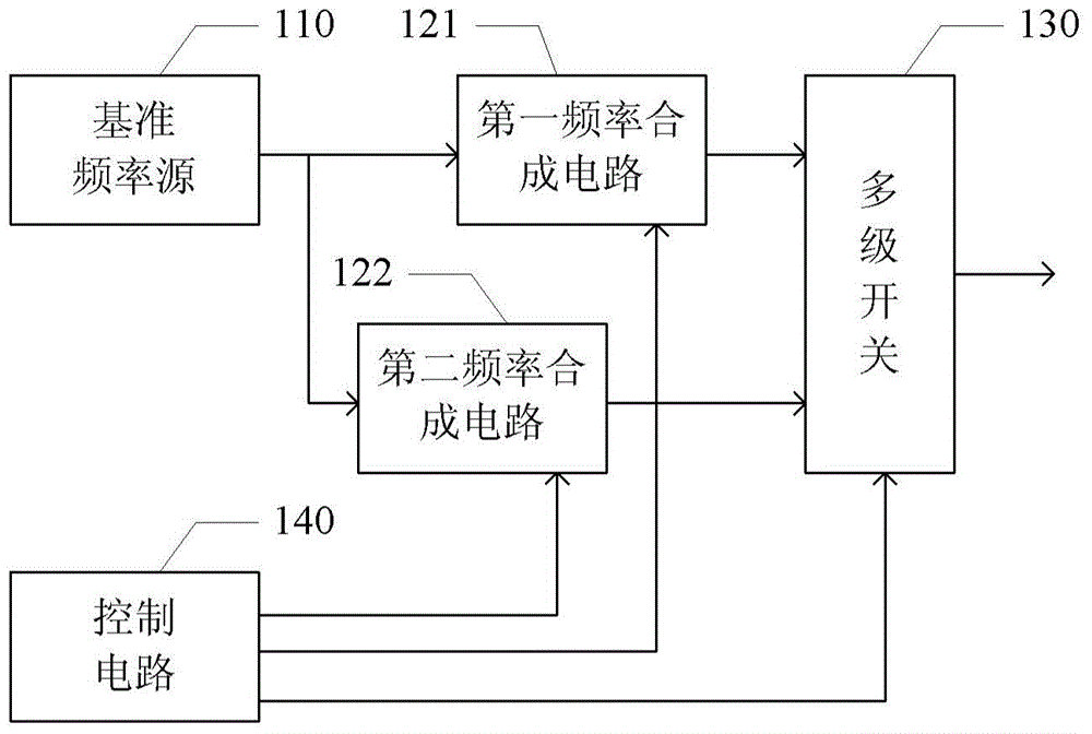
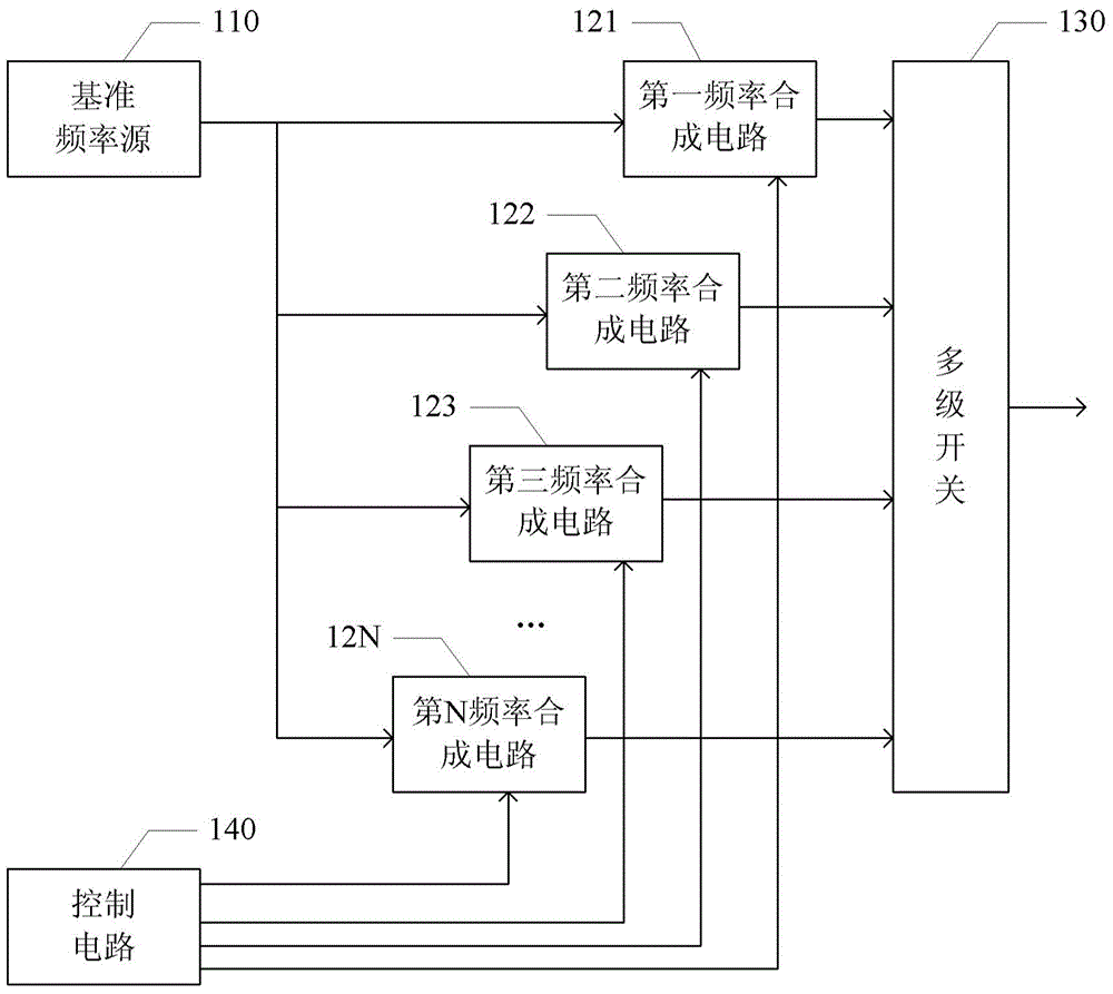
There is provided a circuit for generating a sweep frequency signal. The circuit comprises a reference frequency source operative to generate a reference frequency signal, a first frequency combination circuit operating on a first frequency band, with an input coupled to an output of the reference frequency source, and operative to generate a sweep frequency signal in the first frequency band at its output based on the reference frequency signal, a second frequency combination circuit operating on a second frequency band different from the first frequency band, with an input coupled to the output of the reference frequency source, and operative to generate a sweep frequency signal in the second frequency band at its output based on the reference frequency signal, a multiple-level switch with an input coupled to an output of the first frequency combination circuit and to an output of the second frequency combination circuit, and a control circuit coupled to and controlling the first frequency combination circuit, the second frequency combination circuit and the multiple-level switch to output the sweep frequency signal in the first frequency band and the sweep frequency signal in the second frequency band at an output of the multiple-level switch alternately. According to the embodiments, the sweeping speed is enhanced, and the sweep frequency width is extended while the sweep frequency signal has a high pure spectrum (i.e., with a low noise level).

Description

technical field [0001] The embodiments of the present application relate to microwave technology, and in particular to a circuit for generating a fast frequency-sweeping signal with ultra-wideband and high spectral output purity. Background technique [0002] Sweep frequency signals are often used in broadcasting and communication systems. The frequency sweep signal is usually generated by a phase-locked loop technology composed of a point frequency reference source, a voltage-controlled oscillator, a phase detector, and a filter feedback loop. The combination of these four parts is called a frequency synthesizer (PLL). The sweep width of the PLL is limited by the operating frequency range of the voltage-controlled oscillator, and the noise of the sweep signal is related to the sweep time—small noise requires a long lock-in time, and the noise of the output signal is relatively low to achieve fast sweep frequency. big. [0003] Broadband frequency sweep, fast frequency swe...

Claims


Application Information

Patent Timeline
IPC IPC(8): H03L7/16
CPCH03B23/00H03L7/24H03L7/22H03L7/07H04B1/7136H04B2001/71362
Inventor 赵自然刘文国陈志强李元景吴万龙刘以农桑斌郑磊
Owner NUCTECH CO LTD
Why Eureka
Try Eureka