power conversion device
A technology of power conversion device and conversion unit, which is applied in the direction of output power conversion device, AC power input conversion to DC power output, irreversible DC power input conversion to AC power output, etc., which can solve the problem of poor accuracy and responsiveness. Low-cost structure, high-precision control, and good control responsiveness can be achieved without problems such as variation
- Summary
- Abstract
- Description
- Claims
- Application Information
AI Technical Summary
Problems solved by technology
Method used
Image
Examples
Embodiment approach 1
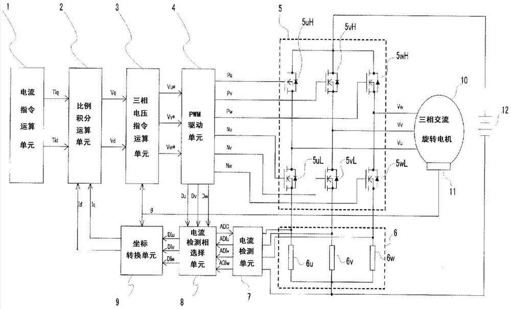
[0055] figure 1 It is a figure which shows the whole structure of the power conversion apparatus in Embodiment 1 of this invention.
[0056] figure 1 Among them, the three-phase AC rotating electrical machine 10 is equipped with a position sensor 11 that detects the magnetic pole position of the motor, and is constituted by, for example, a resolver. The information is output to a control unit (controller) described later.
[0057] The current command calculation unit 1, the proportional integral calculation unit 2, the three-phase voltage command calculation unit 3, the PWM drive unit 4, the current detection unit 7, the current detection phase selection unit 8, and the coordinate conversion unit 9 as the control part of the AC rotating electrical machine are composed of Microcomputer composition.
[0058] The currents flowing through the U, V, and W phases of the three-phase AC rotating electrical machine 10 from the current detecting unit 7 are input to the current detect...
Embodiment approach 2
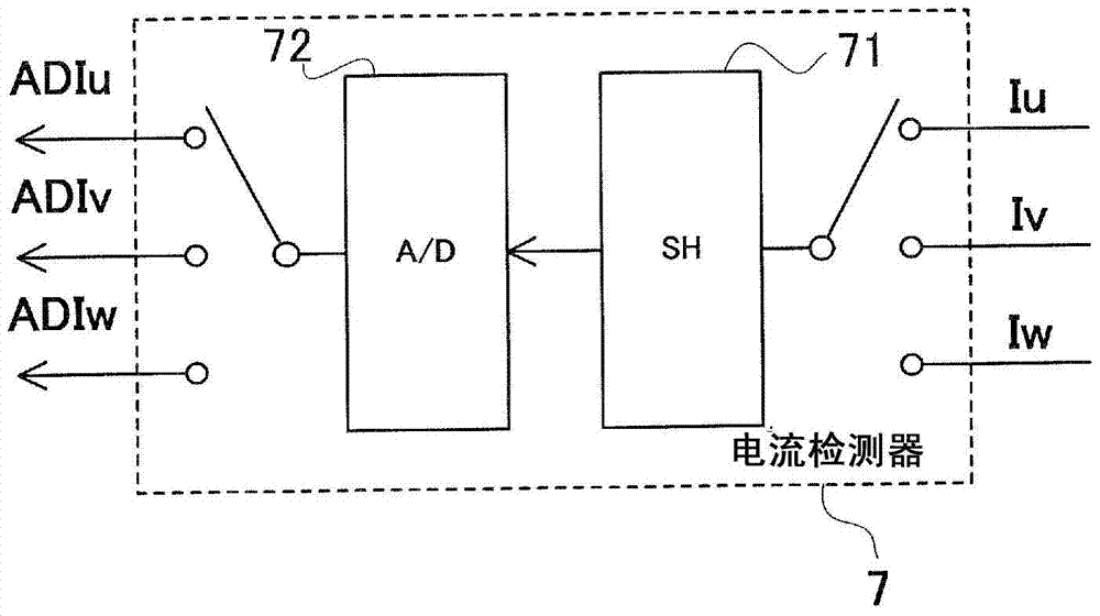
[0133] In Embodiment 1, such as image 3 As shown, the current detection unit 7 is composed of a sample-and-hold circuit and an analog-to-digital conversion circuit, such as Figure 16 As shown, the current detection unit 7 does not include a sample-and-hold circuit, but only an analog-to-digital conversion circuit. In this case, by performing the same control as in the first embodiment, the same effects as those in the first embodiment can be obtained.
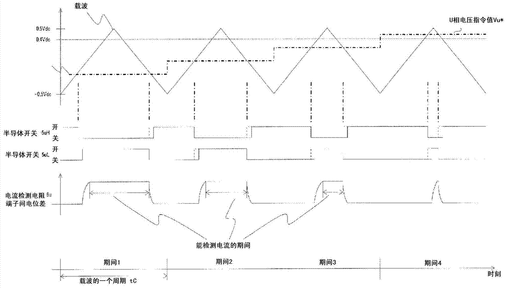
[0134] When a sample-and-hold circuit is provided, it is determined at which time the current value detection process including the current detection value sampling process is performed based on each duty ratio. In the case of a circuit, it is only necessary to determine at which time to perform the analog-to-digital conversion of the current detection value according to each duty cycle, Figure 17 A flowchart illustrating operations in this case is shown.
[0135] Figure 17 , the action is the same as above Figure 8 , ...
Embodiment approach 3
[0147] In Embodiment 1, such as image 3 As shown, the current detection unit 7 is composed of one sample hold circuit 71 and one analog-digital conversion circuit 72, but in the third embodiment, the current detection unit 7C is composed of two sample hold circuits and two analog-digital conversion circuits. The configuration of the circuit will be described.
[0148] In addition, in the third embodiment, the difference from the first embodiment lies in the current detection unit 7 and the current detection phase selection unit 8 , which will only be described below.
[0149] Figure 18 It is a diagram in the following case: the current detection unit 7C is composed of two sampling and holding circuits 71uvC and 71vwC and two analog-to-digital conversion circuits 72uvC and 72vwC, and at least has an input terminal capable of inputting to the two sampling and holding circuits, and an input terminal capable of One output terminal for output from the two analog-to-digital conv...
PUM
 Abstract
Description
Claims
Application Information
 - R&D
- Intellectual Property
- Life Sciences
- Materials
- Tech Scout
- Unparalleled Data Quality
- Higher Quality Content
- 60% Fewer Hallucinations
Browse by: Latest US Patents, China's latest patents, Technical Efficacy Thesaurus, Application Domain, Technology Topic, Popular Technical Reports.
© 2025 PatSnap. All rights reserved.Legal|Privacy policy|Modern Slavery Act Transparency Statement|Sitemap|About US| Contact US: help@patsnap.com


