
Automatic-transmission hydraulic control device

A technology of automatic transmission and oil pressure control, applied in transmission control, mechanical equipment, components with teeth, etc., can solve the problems of oil pressure change, difficulty in suppressing the change of transmission ratio, and deterioration of engine fuel consumption, etc. Achieve the effects of maintaining control stability, suppressing deterioration of controllability, and suppressing fluctuations in hydraulic pressure

Inactive Publication Date: 2014-08-13
TOYOTA JIDOSHA KK
View PDF10 Cites 2 Cited by
  • Summary
  • Abstract
  • Description
  • Claims
  • Application Information

AI Technical Summary

Problems solved by technology

In the device described in Japanese Patent Application Laid-Open No. 2006-70956, the spring constants are different so that the hydraulic pressures in the hydraulic chambers of the driving pulley and the driven pulley do not resonate. If the vibration frequency of the hydraulic pressure in each hydraulic chamber is the same as the vibration frequency of the hydraulic pressure supplied or discharged to each hydraulic chamber, the hydraulic pressure may vary greatly due to resonance.
[0009] In addition, in the device described in the above-mentioned Japanese Patent Laid-Open No. 2000-291474, even if the transmission ratio can be changed to suppress vibration of the belt due to resonance, it cannot suppress the resonance of the oil pressure for setting the transmission ratio and clamping force. And the change of gear ratio and clamping force caused by it
Similarly, in the device described in Japanese Patent Application Laid-Open No. 63-48637, it is difficult to suppress the change of the gear ratio due to the pulsation of the oil pressure, and the gear ratio is changed even by a small amount, so there is a possibility that the engine speed may deviate from the target. Possibility of worsening fuel consumption
[0010] Furthermore, the device described in Japanese Patent Application Laid-Open No. 2000-291474 is configured to suppress the supply pressure vibration and the pulsation of the fuel that vibrates along with the discharge. Unlike this, the supply and discharge are greatly staggered in time. It is difficult to suppress the pulsation of the oil pressure when the fluctuations of the pressure do not affect each other

Method used


Image

  • Automatic-transmission hydraulic control device
  • Automatic-transmission hydraulic control device
  • Automatic-transmission hydraulic control device

Examples


Embodiment Construction

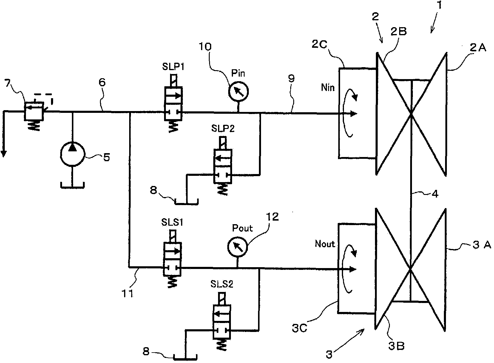
[0032] An example of the automatic transmission that is the object of the present invention is a belt type continuously variable transmission. If its structure is briefly described, it will be as follows: figure 1 As shown, a belt-type continuously variable transmission 1 includes a primary pulley 2 as a driving pulley and a secondary pulley 3 as a driven pulley, and a belt 4 is wound around these pulleys 2 and 3 . The primary pulley 2 includes a fixed pulley 2A integrated with a rotating shaft (not shown), and a movable pulley 2B that moves back and forth in the axial direction on the rotating shaft so as to approach and separate from the fixed pulley 2A. These pulleys 2A, The mutually facing surfaces of 2B are formed in a tapered shape, and the tape winding groove is formed by these tapered surfaces. In addition, a hydraulic chamber 2C is formed on the back side of the movable sheave 2B (the side opposite to the surface facing the fixed sheave 2A), and the movable sheave 2B ...


PUM


Abstract

An automatic-transmission hydraulic control device is configured so as to use the hydraulic pressure of hydraulic chambers provided in pulleys to control the width of pulley grooves around which a belt wrapped around a pair or more of pulleys is wrapped, or the pressure applied to the belt by the pulleys. Furthermore, the automatic-transmission hydraulic control device is provided with: a control valve for controlling the supply of hydraulic pressure to a hydraulic chamber, or the release of hydraulic pressure from the hydraulic chamber; and a drive-frequency setting means for setting the drive frequency of a drive signal for operating the control valve to a frequency in which the phase of the maximum value in the amplitude of the drive signal is offset from the phase of the maximum value in the amplitude of the oscillations accompanying the rotation of the pulleys.

Description

[0001] technological invention [0002] The present invention relates to an oil pressure control device for controlling oil pressure supplied to a driving pulley and a driven pulley and oil pressure discharged from these pulleys in a belt-type continuously variable transmission. Background technique [0003] In the belt-type continuously variable transmission mechanism, a belt is wound around grooves in a drive-side pulley and a driven-side pulley, and the width of the belt winding groove is changed by hydraulic pressure to change a gear ratio. In addition, the belt-type continuously variable transmission mechanism uses hydraulic pressure to set the load (clamping force) that clamps the belt wound on the belt winding groove to a predetermined value, thereby setting the transmission torque capacity in accordance with the input torque. corresponding capacity. And, the gear ratio of the belt-type continuously variable transmission mounted on the vehicle is controlled so that, fo...

Claims


Application Information

Patent Timeline
Patent Type & Authority Applications(China)
IPC IPC(8): F16H61/02
CPCF16H61/66259F16H61/02F16H57/0006F16H2061/0255F16H61/0267F16H61/662
Inventor 木村谦大服部勇仁稻川智一稻垣贵文永里有
Owner TOYOTA JIDOSHA KK
Learn More