
Hydraulic servo device

A hydraulic servo and hydraulic cylinder technology, applied in the direction of fluid pressure actuators, servo motors, fluid pressure actuator system components, etc., can solve the problems of hydraulic servo device control response limitation, control failure, etc.

Inactive Publication Date: 2003-10-15
EBARA CORP
View PDF1 Cites 0 Cited by
  • Summary
  • Abstract
  • Description
  • Claims
  • Application Information

AI Technical Summary

Problems solved by technology

As the rotational speed of the pilot shaft increases, the oil passages on the surface of the pilot shaft move out of alignment with the oil passages in the piston, causing control failure
Therefore, the control response of this hydraulic servo is limited

Method used


Image

  • Hydraulic servo device
  • Hydraulic servo device
  • Hydraulic servo device

Examples


Embodiment Construction

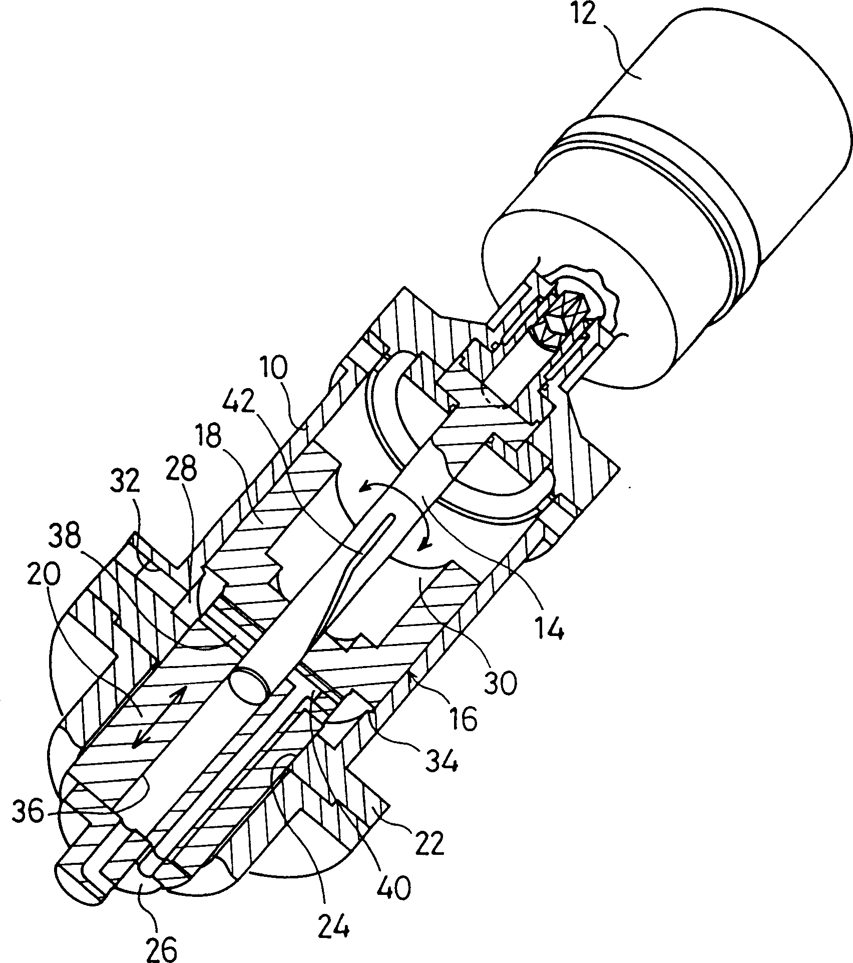
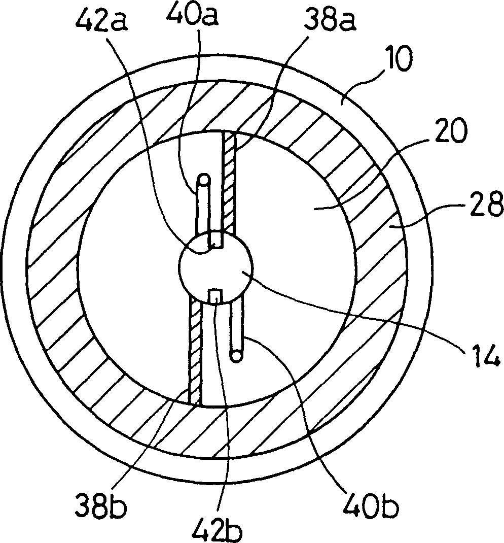
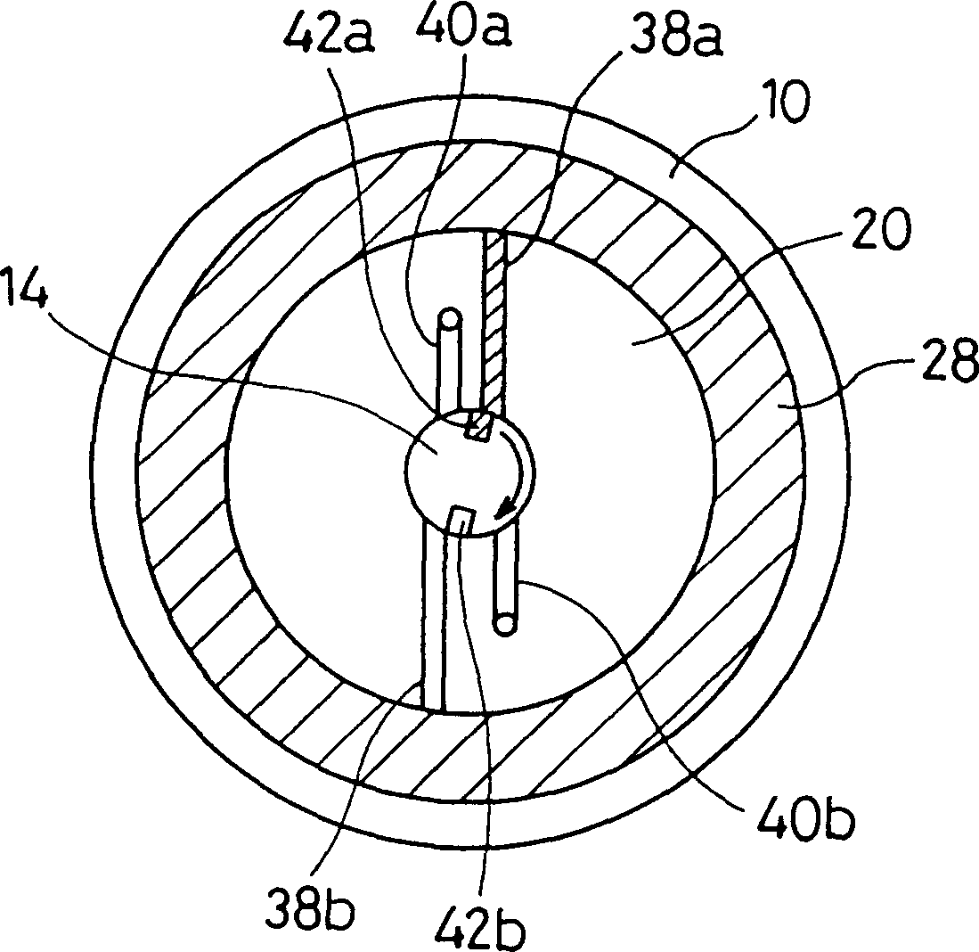
[0032] Such as figure 1 shown, generally used as Figure 11 The hydraulic servo device of the first embodiment of the present invention for the actuating device of the bucket tube of the hydraulic coupling includes a hydraulic cylinder 10 as a high-pressure shell, a proximal end of the hydraulic cylinder 10, and a controller (not shown) a connected guide shaft actuator 12 , a guide shaft 14 extending from the guide shaft actuator 12 into the hydraulic cylinder 10 and a piston 16 located in the space between the hydraulic cylinder 10 and the guide shaft 14 . The piston 16 can slide along the axial direction of the guide shaft 14 , but cannot rotate around the guide shaft 14 . Piston 16 includes a large diameter portion 18 near the proximal end of hydraulic cylinder 10 and a small diameter portion 20 near the distal end of hydraulic cylinder 10 . The small-diameter portion 20 protrudes from the hydraulic cylinder 10 in the axial direction from a sliding hole 24 of an end wall ...


PUM


Abstract

A cylinder houses an angularly movable pilot shaft and a piston axially movably mounted on the pilot shaft. When the pilot shaft is angularly moved, a communication passage defined in an outer circumferential surface of the pilot shaft is brought into communication with an oil supply passage or an oil drain passage for axially moving the piston. The pilot shaft has a pair of communication passages defined in the outer circumferential surface thereof, and the piston has a pair of oil passages defined therein.

Description

technical field [0001] This invention relates to hydraulic servos for converting small torque angular displacements into large load linear displacements, and more particularly to hydraulic servos for manipulating a bucket used as a speed control mechanism for a variable speed fluid coupling. Background technique [0002] Figure 11 Actuators for a water supply to a high capacity boiler are shown. Such as Figure 11 As shown, the rotation of the input shaft 121 is accelerated and transmitted to a driving shaft 123 through a large gear 122 and a small gear 124, and the rotation is then transmitted to a driven shaft 125 through a fluid coupling C. The rotation is then accelerated from the driven shaft 125 and transmitted to an output shaft 132 via a large gear 131 and a small gear 133 . The fluid coupling C includes an impeller 126 and an impeller housing 128 mounted on the driving shaft 123 and a rotor mounted on the driven shaft 125 . When working oil is introduced into the...

Claims


Application Information

Patent Timeline
Patent Type & Authority Patents(China)
IPC IPC(8): F15B15/14F15B21/044F15B9/10F15B11/12F16D33/14
CPCF15B21/044F15B9/10F15B11/121
Inventor 绪方大洋木村克己杉山和彦服部和男
Owner EBARA CORP
Learn More