
Remote pneumatic feeding and weighing feeder

A feeding machine and weighing technology, applied in conveyors, feeders, automatic feeding/discharging weighing equipment, etc., can solve the problem of increasing user investment costs, climbing of feeding pipelines, complex machine structure, etc. problems, to achieve the effect of saving manpower, reducing labor intensity, and high degree of automation

Inactive Publication Date: 2015-03-04
JIANGSU HENGSHENYANG MACHINERY
View PDF6 Cites 14 Cited by
  • Summary
  • Abstract
  • Description
  • Claims
  • Application Information

AI Technical Summary

Problems solved by technology

[0003] Although the existing pneumatic feeding machines can transport feed over a long distance and scatter feed at 360°, there are many problems: ①The motor impeller throwing plate is erected very high by using a tripod structure, and the center of gravity of the machine moves upward. It is easy to cause an accident of tipping and sinking the machine; ②The material delivery pipeline climbs up, which is easy to cause blockage; ③Using multiple floating balls, although the tipping problem is solved, it increases the user's investment cost, the machine structure is complicated, and the installation is very inconvenient; ④When starting up, start the impeller throwing motor first, and then start the feeding motor after working for about one minute. This two-step manual control operation is too cumbersome; There is a large amount of feed that cannot be sucked away in the pipeline, which is easy to agglomerate and cause the blockage of the feeding pipeline; ⑥There is no pneumatic feeding machine for feeding by weight; ⑦The feeding machine used is to control the time of each start-up The length of feed depends on manual experience, and the amount of feeding is controlled by mechanical adjustment. It can only roughly control the amount of feeding each time. If the timer stops, it will cause a box of feed to be fed all at once, resulting in great waste. ; If there is a trip on the way of feeding and the timer runs faster, it will cause insufficient feed

Method used


Image

  • Remote pneumatic feeding and weighing feeder
  • Remote pneumatic feeding and weighing feeder
  • Remote pneumatic feeding and weighing feeder

Examples


Embodiment Construction

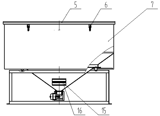
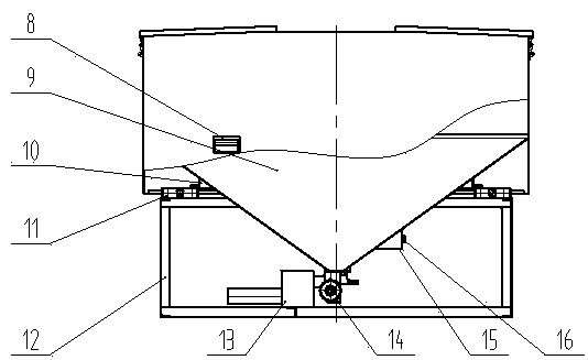
[0017] like Figure 1-6 As shown, the remote pneumatic feed meter feeding machine includes a weight feed box 1, a feed pipeline 2, a pneumatic throwing machine 3 and a control box 4, which are connected to the feed output pipe 12 of the weight feed box 1 The feeding pipeline 2, one end of the feeding pipeline 2 is connected to the receiving output pipe 13 of the weighing feed box 1, the other end of the feeding pipeline 2 is connected to the feeding interface pipe 17 of the pneumatic throwing machine 3, and the wiring in the control box 4 The terminals are respectively connected to the connecting terminal 16 of the weighing feeding box 1 and the motor of the pneumatic throwing machine 3, and the input terminal of the control box 4 is connected to the three-phase power grid to form a remote pneumatic feeding meter re-throwing feeder as a whole.

[0018] In the remote pneumatic feeding meter weighing feeder of the present invention, the weighing feeding box 1 includes a box cove...


PUM


Abstract

The invention discloses a remote pneumatic feeding and weighing feeder. The remote pneumatic feeding and weighing feeder is characterized in that a material collecting output pipe (13) of a weighing feeding tank (1) is connected with a material transport pipeline (2), one end of the material transport pipeline (2) is connected to the material collecting output pipe (13) of the weighing feeding tank (1), the other end of the material transport (2) is connected with a feeding connector pipe (17) of a pneumatic material throwing machine (3), connecting terminals in a control box (4) are respectively connected with a connecting terminal (16) of the weighing feeding tank (1) and a motor of the pneumatic material throwing machine (3), an input end of the control box (4) is connected with a three-phase power grid, and the remote pneumatic feeding and weighing feeder is integrally formed. According to the remote pneumatic feeding and weighing feeder disclosed by the invention, remote large-area weighing feeding is realized, installing and use are convenient, the automation degree is high, the labor intensity is low, the labor is saved, the feeding distance is far, and market needs are wide.

Description

technical field [0001] The invention relates to a feeding machine, in particular to a refeeding machine with a remote pneumatic feeding meter. Background technique [0002] In the field of aquaculture, feeding machines have become an indispensable farming machinery in the aquaculture industry. The feeding machines currently used are all fixed on the feeding platform, the feeding fan is not more than 120 o, the distance is less than 22 meters, and the load water surface of one set is less than 20 mu. A pond with a large water surface needs several feeding machines, and in the pond The feeding platform is built in the central part to install the feeding machine, and it is extremely inconvenient to transport and feed the feed. In a word, the currently used feeding machine cannot fully, rationally and scientifically use the feed. This control method cannot control the amount of feed, which forms a bottleneck for the realization of scientific fish farming. Thereby need a kind o...

Claims


Application Information

Patent Timeline
IPC IPC(8): A01K61/02G01G13/16B65G53/24B65G53/52B65G53/66B65G31/04
CPCA01K61/80B65G31/04B65G53/24B65G53/52B65G53/66G01G13/16
Inventor 成之阳成美玲
Owner JIANGSU HENGSHENYANG MACHINERY
Learn More