Sewage back-flushing filtering device
A filtering device and pipe flushing technology, which is applied in fish farming, application, animal husbandry, etc., can solve the problems of increasing the gas-liquid contact area, high noise, and not effectively using gravity to filter impurities, etc., to achieve a good mute effect and reduce noise effect
- Summary
- Abstract
- Description
- Claims
- Application Information
AI Technical Summary
Problems solved by technology
Method used
Image
Examples
Embodiment 1
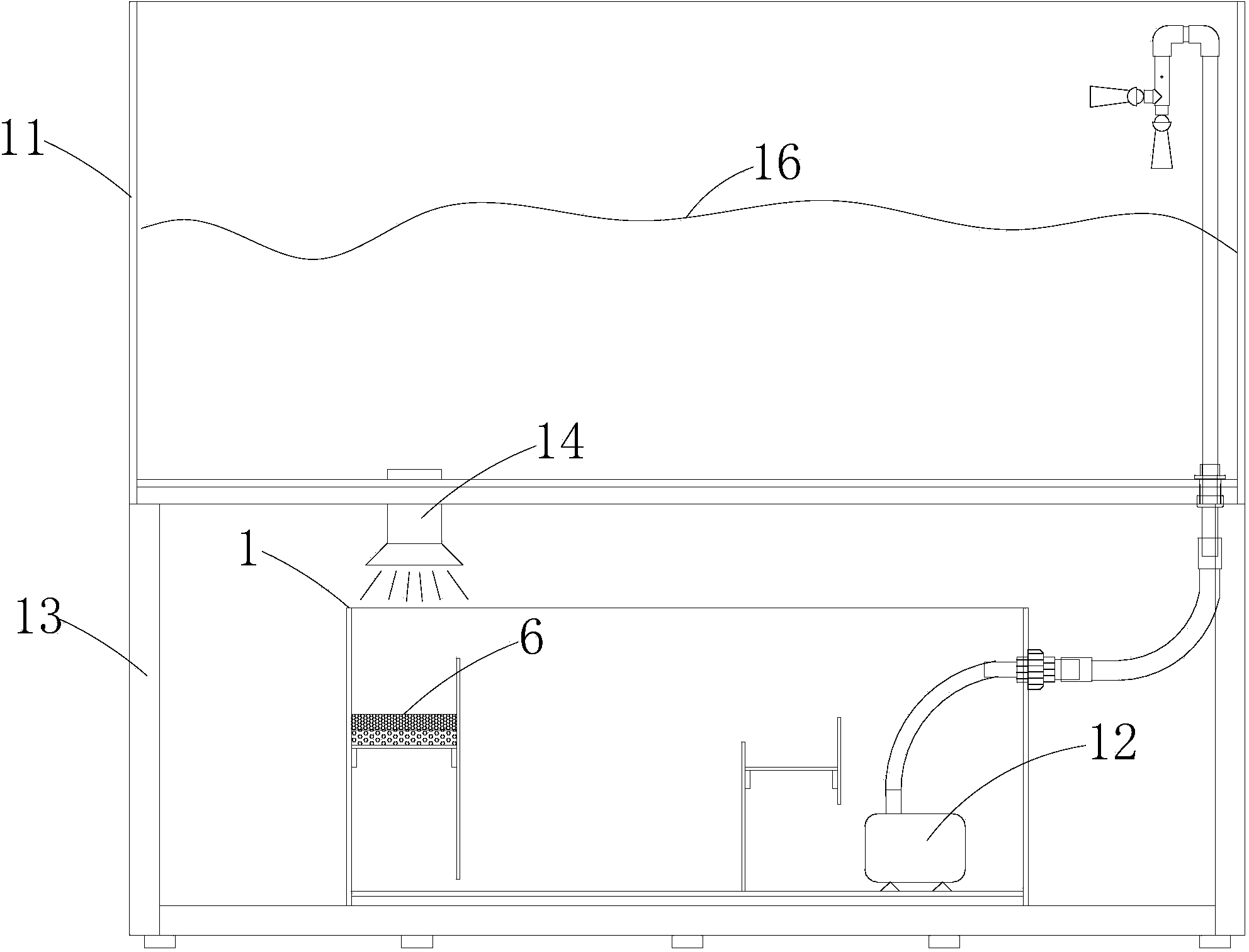
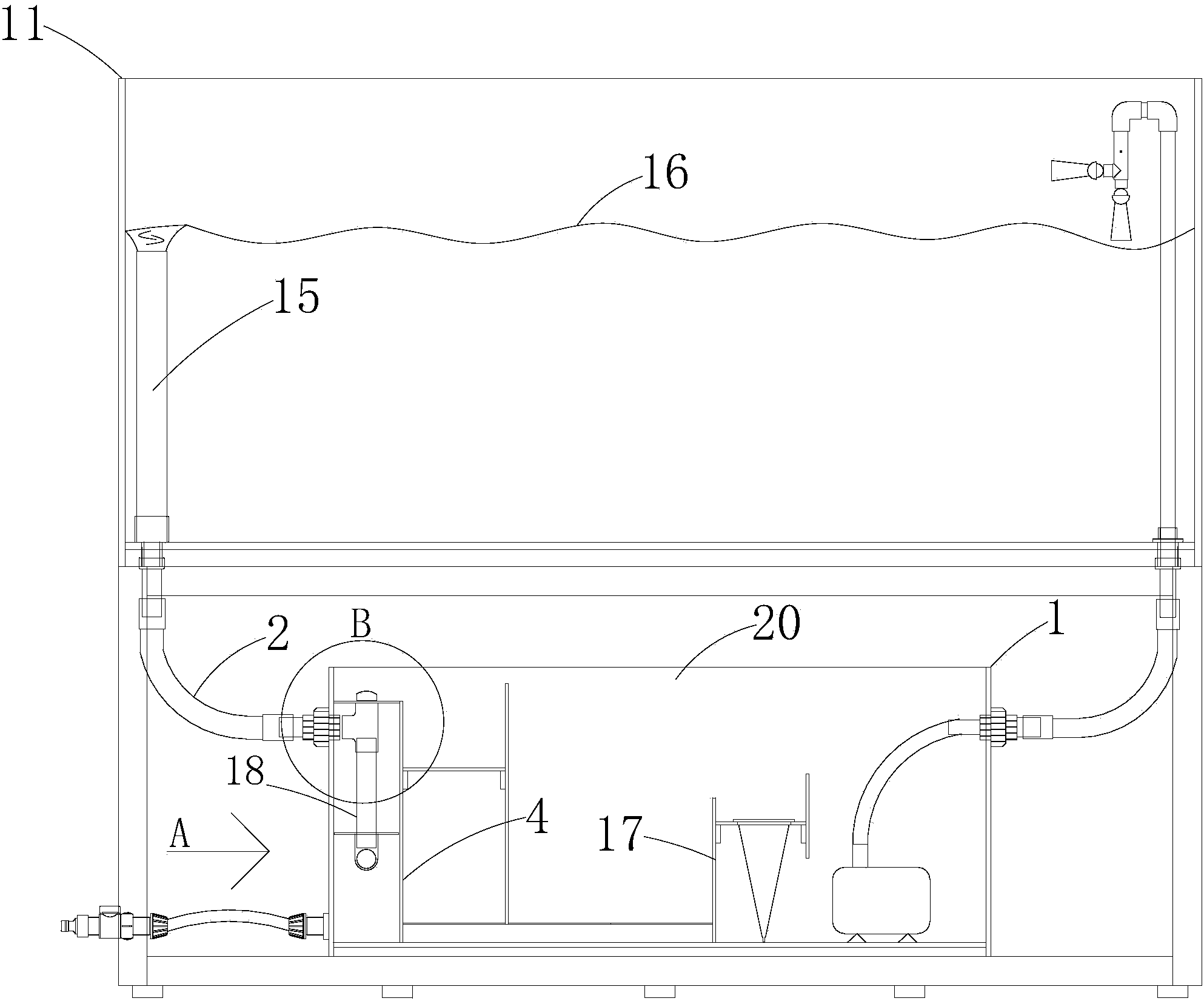
[0042] like Image 6 A sewage backflushing filter device as shown includes a partition 17 and a housing 1 with a cavity inside, the partition 17 divides the cavity into at least two chambers, on the wall of the housing There is a water inlet hole for external liquid to enter (the hole in the side wall of the casing 1 inserted into the right end of the water inlet pipe 2 is the water inlet hole), and the chamber connected with the water inlet hole is the first chamber 5, which is tightly closed. The baffle plate adjacent to the first chamber 5 is the first baffle plate 4 , and a first gap 7 through which the liquid overflows is provided above the first baffle plate 4 . In the present invention, the sewage inlet hole is arranged on the shell wall, and the flow of the sewage is as follows: from the inlet hole to the first chamber and then overflowing through the first gap on the first partition plate, and then the next filtration process is performed; Compared with the prior art...
Embodiment 2
[0049] like Figure 7 As shown, the first chamber 5 is provided with a backflushing pipe 8 , the water inlet of the backflushing pipe 8 is connected to the water inlet hole, and the water outlet of the backflushing pipe 8 is connected to the first chamber 5 . combined with figure 2 , with Figure 7 is attached figure 2 A partial enlarged view of the first chamber 5 and the second chamber adjacent to the first chamber, but with attached Figure 7 The structure in the first chamber is different from the attached figure 2 The structure of the inner first chamber.
Embodiment 3
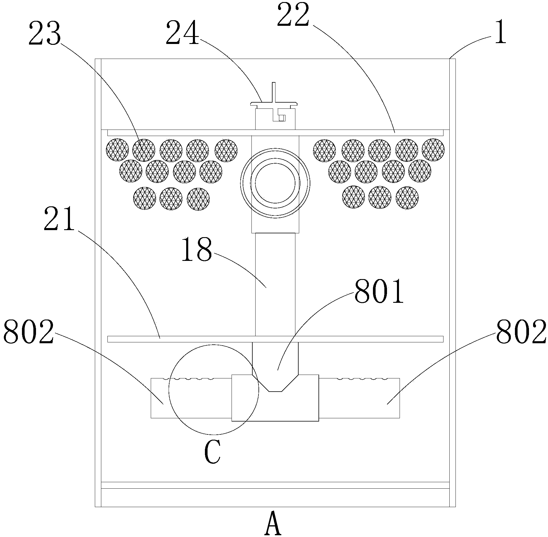
[0051] like image 3 shown, image 3 Yes figure 2 In the schematic diagram of the middle A direction, the difference between the embodiment 3 and the embodiment 2 is that the recoil pipe 8 of the embodiment 3 includes a tee pipe 801 and two transverse pipes 802, and the tee pipe 801 includes an inlet and two The two horizontal pipes 802 are respectively inserted into the two outlets of the three-way pipe 801; the water outlet of the backflushing pipe is set on the horizontal pipe, and the liquid flows from the inlet of the three-way pipe. into the cavity from the water outlet on the cross tube. like Figure 4 As shown, the water outlet is a through hole 25 opened on the horizontal pipe. The opening of the through hole one 25 faces upward. This facilitates the formation of a static flow sedimentation layer under the horizontal pipe, and the overflowing clean water above the horizontal pipe. At least two through holes are included, and the through holes are evenly distrib...
PUM
 Abstract
Description
Claims
Application Information
 - R&D
- Intellectual Property
- Life Sciences
- Materials
- Tech Scout
- Unparalleled Data Quality
- Higher Quality Content
- 60% Fewer Hallucinations
Browse by: Latest US Patents, China's latest patents, Technical Efficacy Thesaurus, Application Domain, Technology Topic, Popular Technical Reports.
© 2025 PatSnap. All rights reserved.Legal|Privacy policy|Modern Slavery Act Transparency Statement|Sitemap|About US| Contact US: help@patsnap.com


