
Metal plate stamping die

A stamping die and sheet metal technology, applied in the direction of forming tools, manufacturing tools, metal processing equipment, etc., can solve the problems of unguaranteed stamping effect and stamping efficiency, raw material sheet metal fracture, etc., and achieve high stamping efficiency and stamping effect. Good, improve the effect of stamping quality

Inactive Publication Date: 2015-03-04
吴中区光福华宇钣金厂
View PDF6 Cites 5 Cited by
  • Summary
  • Abstract
  • Description
  • Claims
  • Application Information

AI Technical Summary

Problems solved by technology

However, the traditional stamping dies are relatively simple, and it is easy to cause the raw material sheet metal to break during the stamping process, and it can only handle a small amount of production. When dealing with mass production, the stamping effect and stamping efficiency cannot be guaranteed.

Method used


Image

  • Metal plate stamping die
  • Metal plate stamping die
  • Metal plate stamping die

Examples


Embodiment Construction

[0016] The present invention is described below in conjunction with accompanying drawing.

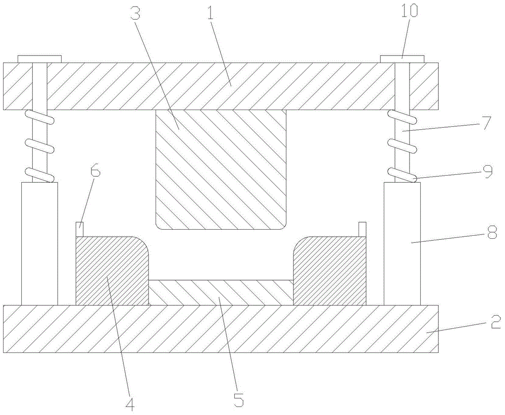
[0017] as attached image 3 The illustrated sheet metal stamping die of the present invention includes an upper template 1, a lower template 2, a guide post device, a punch 3 and a die assembly; the upper template 1 and the lower template 2 pass through the guide post device Connected; the bottom of the upper template 1 is provided with a punch 3; the lower template 2 is provided with a die assembly; the die assembly includes a concave module 4, a bottom plate 5 and a positioning block 6; the concave module 4 is provided with two pieces; the bottom plate 5 is arranged between two concave modules 4; the height of the concave module 4 is greater than the height of the bottom plate 5; the positioning block 6 is arranged on each concave module 4; The corners where the two sides of the die 3 meet the lower surface are rounded; the corners where the inner side of the concave module 4 meets t...


PUM


Abstract

The invention discloses a metal plate stamping die which comprises an upper die plate, a lower die plate, guide column devices, a male die and a female die assembly. The upper die plate is connected with the lower die plate by the guide column devices; the male die is arranged on the lower side of the upper die plate; the female die assembly is arranged on the lower die plate; the female die assembly comprises two female die blocks, a bottom plate and positioning blocks; the bottom plate is arranged between the two female die blocks; each female die block is higher than the bottom plate; each positioning block is arranged on the corresponding female die block; joint corners of two side surfaces and the lower surface of the male die are rounded corners; joint corners of the inner side surfaces and the upper surfaces of the female die blocks are rounded corners. The metal plate stamping die has the advantages that good stamping effects can be realized, the stamping quality can be improved, and the metal plate stamping die is high in stamping efficiency and suitable for stamping metal plates on a large scale.

Description

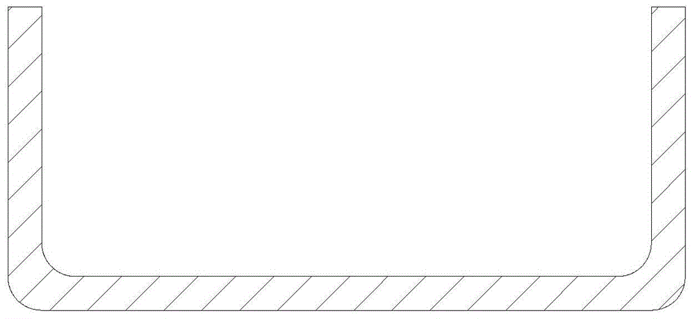
technical field [0001] The invention relates to a stamping die, in particular to a sheet metal stamping die used in the process of making sheet metal into a U-shaped bending bracket. Background technique [0002] Made as attached figure 1 When the U-shaped bending bracket is described, it is necessary to attach figure 2 Raw sheet metal shown is bent. In the past, due to the influence of equipment factors, manual bending was usually used, but such work is too difficult, time-consuming and laborious, and the bending effect is poor. With the development of society and the advancement of technology, the bending can be realized by stamping the template, and the operation of the stamping die reduces the difficulty of work and saves time and effort. However, the traditional stamping dies are relatively simple, and the raw material sheet metal is likely to break during the stamping process, and it can only handle a small amount of production. When dealing with mass production, t...

Claims


Application Information

Patent Timeline
IPC IPC(8): B21D37/10B21D5/02B21D43/00
CPCB21D37/10B21D37/12
Inventor 姚建芬
Owner 吴中区光福华宇钣金厂
Learn More