Equal-modulus-gear fluid mechanism and engine employing same

A fluid mechanism and engine technology, which can be used in machines/engines, liquid fuel engines, combustion engines, etc., and can solve problems such as processing difficulties and seal wear.

Active Publication Date: 2015-03-04
吴江科技创业园管理服务有限公司
View PDF4 Cites 4 Cited by
  • Summary
  • Abstract
  • Description
  • Claims
  • Application Information

AI Technical Summary

Problems solved by technology

[0002] Many types of traditional equal-modulus gear fluid mechanisms are widely used, but there are problems of sealing

Method used


Image

  • Equal-modulus-gear fluid mechanism and engine employing same
  • Equal-modulus-gear fluid mechanism and engine employing same
  • Equal-modulus-gear fluid mechanism and engine employing same

Examples


Embodiment 1

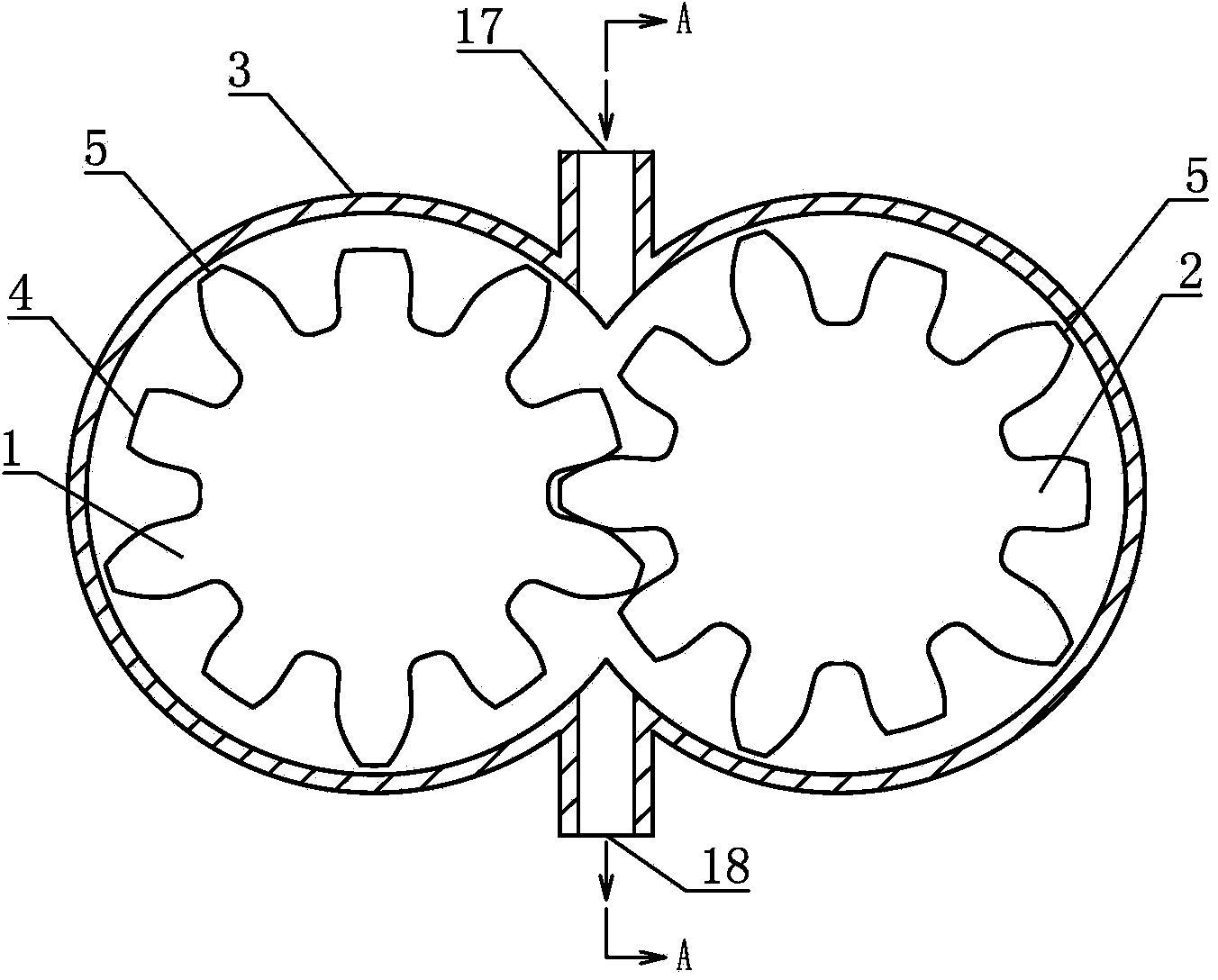
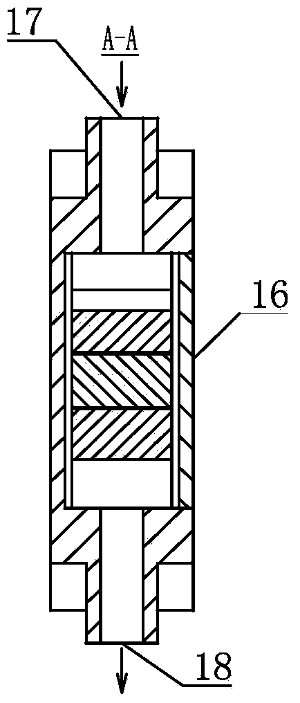
[0074] Such as Figure 1.1 with Figure 1.2 As shown, an equal-modulus gear fluid mechanism includes a gear A1 and a gear B2, the module of the gear A1 is the same as that of the gear B2, and the number of teeth of the gear A1 is the same as that of the gear B2 , a part of the teeth on the gear A1 is truncated to form a half tooth 4, a tooth that has not been truncated is defined as a full tooth 5, and a part of the teeth on the gear B2 is truncated to form a half tooth 4, The teeth that are not truncated are defined as full teeth 5, the gear A1 and the gear B2 are arranged in the double cylindrical cavity 3, and the gear A1 and the gear B2 are mutually meshed and rotated. A fluid inlet 17 is provided on the double-cylindrical cavity 3 , and a fluid outlet 18 is provided on the double-cylindrical cavity 3 .

[0075] As a changeable embodiment, optionally, a fluid inlet 17 is provided on the end sealing body 16 of the double cylindrical cavity 3; or on the double cylindrical c...

Embodiment 2

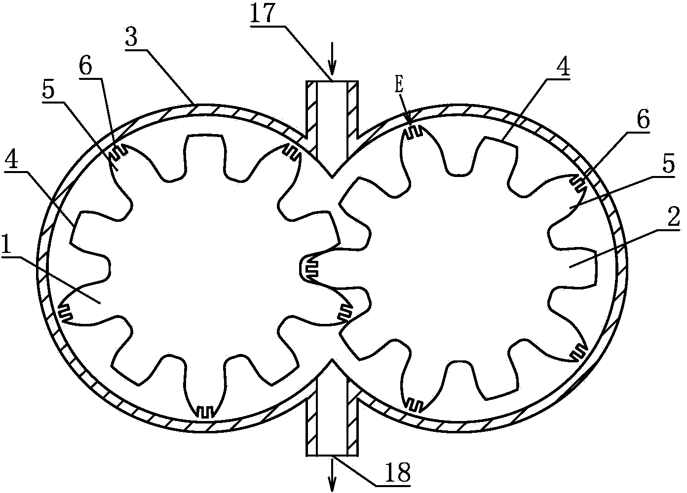
[0079] Such as Figure 2.1 with Figure 2.2 As shown, an equal-modulus gear fluid mechanism differs from Embodiment 1 in that a seal is provided on the tooth tops of the full teeth 5 on the gear A1 along the axis of rotation of the gear A1. Concave-convex resistance-increasing lines 6 , sealing concave-convex resistance-increasing lines 6 are provided on the tops of all teeth 5 on the gear B2 along the axis of rotation of the gear B2 .

[0080] As a changeable embodiment, it is also possible to set a sealing concave-convex resistance increasing line 6 on the tooth tip of the full tooth 5 on one of the gear A1 and the gear B2 along the axis of rotation of the gear. .

[0081] In the present invention, all embodiments can refer to this embodiment along the gear A1 and / or the gear B1 on the tooth top of the full tooth 5 on the gear A1 and / or on the gear B1 Sealing concave-convex resistance-increasing lines 6 are arranged in the axis direction of the rotation.

Embodiment 3

[0083] Such as Figure 3.1 with Figure 3.2 As shown, an equal-modulus gear fluid mechanism differs from Embodiment 1 in that a concave-convex resistance-increasing structure 7 is provided on the end surface of the gear A1.

[0084] As a changeable embodiment, at least one of the three of the end face of the gear A1, the end face of the gear B2 and the inner wall of the end sealing body 16 can be provided with the concave-convex resistance increase Structure 7.


PUM


Abstract

A disclosed equal-modulus-gear fluid mechanism comprises a gear A and a gear B, the modulus of the gear A and the modulus of the gear B are same, and the tooth number of the gear A and the tooth number of the gear B are same; the teeth of the gear A are partially subjected to top cutting to form half teeth, and the teeth which are not subjected to top cutting are defined as complete teeth; the teeth of the gear B are partially subjected to top cutting to form half teeth, and the teeth which are not subjected to top cutting are defined as complete teeth; the gear A and the gear B are arranged in a double-cylinder-shaped chamber in a mutually-engaged rotary way; and the double-cylinder-shaped chamber and/or an end-part sealed body of the double-cylinder-shaped chamber are provided with fluid inlets, and the double-cylinder-shaped chamber and/or the end-part sealed body of the double-cylinder-shaped chamber are provided with fluid outlets. The disclosed equal-modulus-gear fluid mechanism is simple in structure, reliable, low in manufacture production cost and high in efficiency.

Description

technical field [0001] The invention relates to the field of thermal energy and power, in particular to an equimodulus gear fluid mechanism and an engine using the same. Background technique [0002] Many types of traditional equal-modulus gear fluid mechanisms are widely used, but there are problems of sealing and wear and difficult processing. Therefore, it is necessary to invent a new type of equal-modulus gear fluid mechanism. Contents of the invention [0003] In order to solve the above problems, the technical scheme proposed by the present invention is as follows: [0004] Scheme 1, an equal-modulus gear fluid mechanism, including a gear A and a gear B, the module of the gear A is the same as that of the gear B, and the number of teeth of the gear A is the same as that of the gear B , a part of the teeth on the gear A is truncated to form a half tooth, and a tooth that has not been truncated is defined as a full tooth, and a part of the teeth on the gear B is trunc...

Claims


Application Information

Patent Timeline
IPC IPC(8): F01C1/18F04C2/18F04C18/18F02B53/00
CPCF01C1/18F02B53/00F04C2/18F04C18/18Y02T10/12
Inventor 靳北彪
Owner 吴江科技创业园管理服务有限公司
Why Eureka
Try Eureka