Polarized light-emitting device

A light-emitting device and polarization technology, applied in the field of light-emitting, can solve problems such as low efficiency

Inactive Publication Date: 2015-03-04
杨毅
View PDF5 Cites 4 Cited by
  • Summary
  • Abstract
  • Description
  • Claims
  • Application Information

AI Technical Summary

Problems solved by technology

However, since liquid crystals can only be illuminated with polarized light, and phosphor mate

Method used


Image

  • Polarized light-emitting device
  • Polarized light-emitting device
  • Polarized light-emitting device

Examples


Embodiment Construction

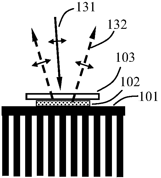
[0015] The present invention proposes a polarized light-emitting device, the structural schematic diagram of the first embodiment is as follows figure 1 shown. The polarized light-emitting device includes an excitation source (not shown in the figure) and a wavelength conversion device for emitting laser light 131 (indicated by a solid line in the figure, hereinafter also) and a wavelength conversion device. A wavelength conversion layer 102 on the device and a wire grid polarizer 103 on the wavelength conversion layer.

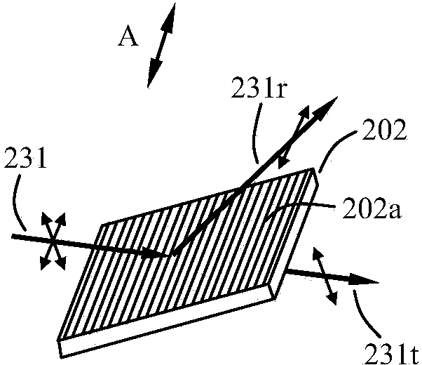
[0016] Here it is necessary to explain the working principle of the wire grid polarizer, such as figure 2 shown. The wire grid polarizer 202 includes a base and a wire grid 202a located on the upper surface of the base. These wire grids are made of metal, generally aluminum, and they are finely arranged in parallel along a specific direction A. When the non-polarized light 231 is incident on the wire grid polarizer 202, the non-polarized light 231 can be...


PUM


Abstract

The invention provides a polarized light-emitting device. The polarized light-emitting device comprises an excitation source for emitting laser light, and a wavelength conversion device, wherein the wavelength conversion device comprises a heat-dissipating device, a wavelength conversion layer positioned on the heat-dissipating device, and a wire grid polarizer positioned on the wavelength conversion layer; the laser light emitted by the laser source enters the wire grid polarizer; the electric vector direction of the laser light is vertical to the wire grid trend of the wire grid polarizer in order that the laser light can enter the wavelength conversion layer through the wire grid polarizer, and is excited to emit excited light. By adopting the polarized light-emitting device, light penetrating through the wire grid polarizer in non-polarized light emitted from the wavelength conversion layer is polarized light in a specific polarization direction, other light is reflected back to the wavelength conversion layer by the wire grid polarizer to be scattered and reflected, a part of specific polarized light is transmitted out after the other light is emitted from the wire grid polarizer, and most light is emitted in the form of polarized light after repeated circulation.

Description

[0001] technical field [0002] The invention relates to the field of light emitting technology, in particular to a polarized light emitting device. [0003] Background technique [0004] At present, in the field of luminescent technology, using excitation light to excite phosphor materials has become a commonly used technology, especially in the field of projection display, this technology has unique advantages. In the field of projection display, liquid crystal projection display accounts for about half of the market share. However, since liquid crystals can only be illuminated with polarized light, and phosphor materials emit light as unpolarized light, the efficiency of the combination of the two is very low. [0005] Contents of the invention [0006] In order to solve the above problems, the present invention proposes a polarized light emitting device, including an excitation source for emitting laser light and a wavelength conversion device, the wavelength conver...

Claims


Application Information

Patent Timeline
IPC IPC(8): F21K99/00G03B21/20
Inventor 杨毅
Owner 杨毅
Why Eureka
Try Eureka