Metal homogenizing and melting furnace

A technology for melting furnaces and metals, applied in furnaces, crucible furnaces, furnace components, etc., can solve problems such as molecular structure state and uneven distribution, high labor intensity of workers, and component quality defects, so as to reduce the risk of splashing and hurting people Risk, good heat preservation effect, light weight effect

Active Publication Date: 2015-03-04
如东县东广物流有限公司
View PDF5 Cites 9 Cited by
  • Summary
  • Abstract
  • Description
  • Claims
  • Application Information

AI Technical Summary

Benefits of technology

This new design for an aluminum smelting process improves efficiency while reducing workload and risks associated therewith during operation. Additionally, it reduces the likelihood of moles or particles from entering the system through gaps between components, resulting in better productivity. Overall, this technology simplifies maintenance management processes and increases production rates without sacrificing safety standards.

Problems solved by technology

This patented technical problem addressed by this patents relating to conventional methods used for producing pure iron (Fe) or other alloys involves issues such as uneven temperature distributions caused by solidification of melted materials when they cool down quickly over time, difficulty handling heavy objects that may damage them upon removal through manual tools like shovels, while maintaining consistently good performance under extreme conditions.

Method used


Image

  • Metal homogenizing and melting furnace
  • Metal homogenizing and melting furnace
  • Metal homogenizing and melting furnace

Examples


Embodiment Construction

[0029] The present invention will be further described in detail below in conjunction with the accompanying drawings and examples. The following examples are explanations of the present invention and the present invention is not limited to the following examples.

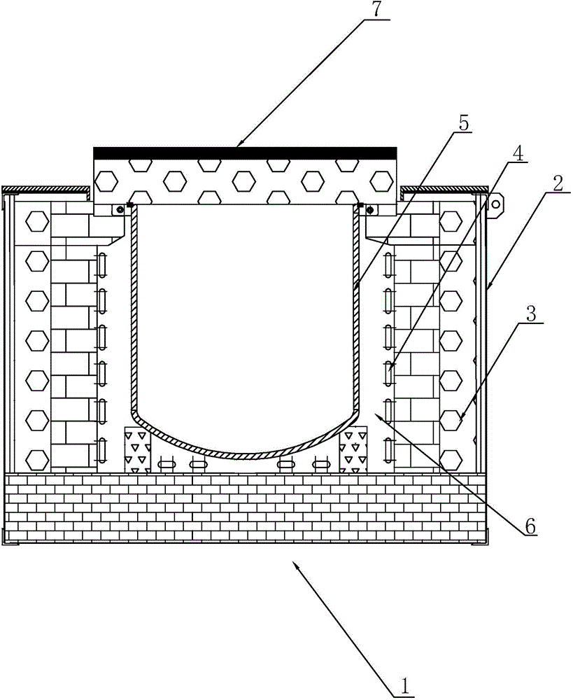
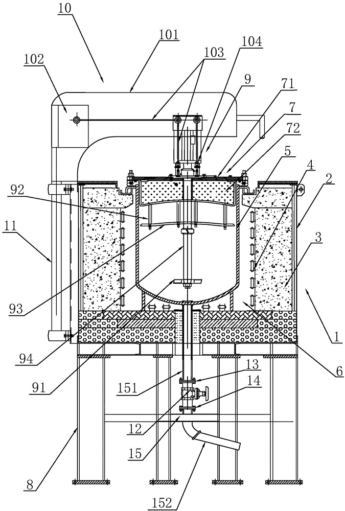
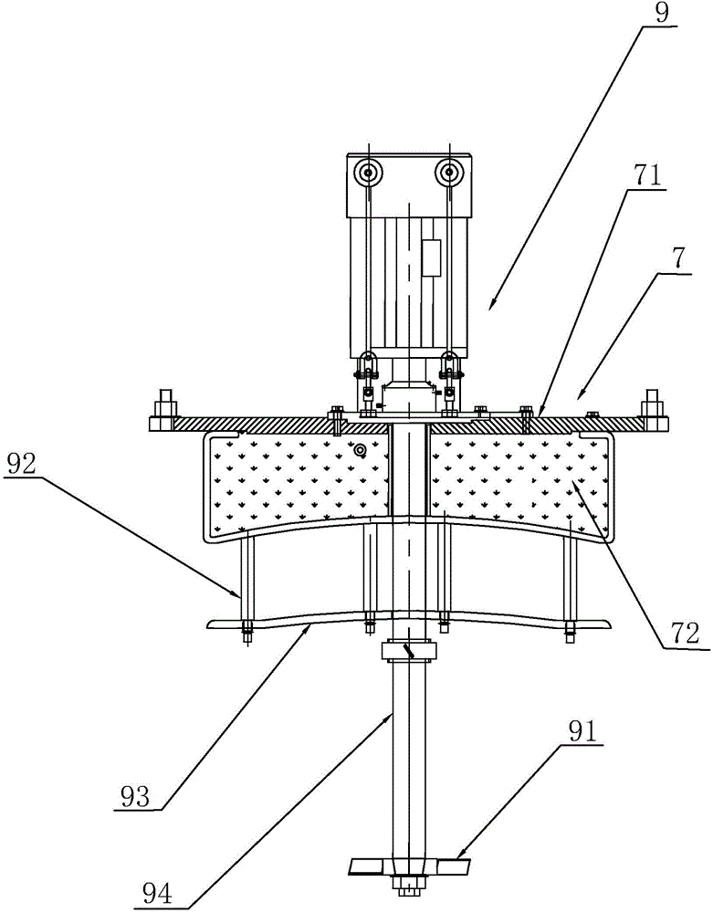
[0030] Such as figure 2 , image 3 The metal homogeneous melting furnace shown is a well-type crucible melting furnace, which includes a furnace body 1 and a bracket 8 for fixing the furnace body 1. The furnace body 1 is sequentially provided with a furnace shell 2, a furnace lining 3, Heating element 4 and crucible 5 . The space in the furnace lining 3 forms a well-shaped furnace 6, the crucible 5 is arranged at the center of the furnace 6, and the heating element 4 is arranged around the outer surface of the crucible 5. The crucible 5 is provided with a furnace cover 7, and the furnace cover 7 is provided with Stirrer 9 , the stirring shaft 94 of the stirrer 9 extends into the crucible 5 and stirs the molten me...


PUM


Abstract

The invention relates to a metal homogenizing and melting furnace. The metal homogenizing and melting furnace comprises a furnace body and a support for fixing a furnace body, wherein the furnace body is sequentially provided with a furnace housing, a furnace lining, a heating element and a crucible from outside to inside, the heating element is arranged around the outer surface of the crucible, the crucible is provided with a furnace cover, a liquid outlet pipeline is arranged at the bottom of the furnace body and penetrates through the furnace housing, the furnace lining and the crucible so as to be communicated with the outside, and a liquid discharging valve is arranged on the liquid outlet pipeline. The liquid outlet pipeline and the liquid discharging valve are arranged at the bottom of the furnace so that the liquid discharging valve can be switched on according to required flows after metal solid is molten, liquid can flow into a special forming module, the labor intensity of workers can be reduced, and the risk that molten metal is splashed out and hurts the workers.

Description


Claims


Application Information

Patent Timeline
Owner 如东县东广物流有限公司
Why Eureka
Try Eureka