An Inverse Synthetic Aperture Radar Azimuth Calibration Method

An inverse synthetic aperture and azimuth technology, applied in the direction of reflection/re-radiation of radio waves, use of re-radiation, measurement devices, etc., can solve the problem of inability to perform correct estimation, not considering the compensation of the secondary phase term, and the complex motion estimation error of the target large problems, to achieve the effects of accurate imaging results, short time, and high estimation accuracy

Active Publication Date: 2017-05-24
NO 20 RES INST OF CHINA ELECTRONICS TECH GRP
View PDF3 Cites 0 Cited by
  • Summary
  • Abstract
  • Description
  • Claims
  • Application Information

AI Technical Summary

Problems solved by technology

The first type uses narrow-band radar to obtain the change of the rotation angle of the moving target from the tracking data. This method can only approximate the change of the rotation angle caused by the change of the target relative to the radar line of sight, but is powerless for the change of the rotation angle caused by the rotation of the target itself, and For the complex motion of the target, the estimation error is often large, and even the correct estimation cannot be performed.
The second type of method uses the isolated point tracking method, which uses the third isolated scattering point on the tracking target (the first two points are used for translation and rotation compensation), and then obtains the rotation angle information; but it is difficult to find a very good isolated point in practice Scattering points, so it is rarely used in actual situations
However, this method does not consider the compensation of the quadratic phase term caused by the rotation speed, and the quadratic phase term will broaden the imaged azimuth image, especially at the edge of the target.

Method used


Image

  • An Inverse Synthetic Aperture Radar Azimuth Calibration Method
  • An Inverse Synthetic Aperture Radar Azimuth Calibration Method
  • An Inverse Synthetic Aperture Radar Azimuth Calibration Method

Examples


Embodiment Construction

[0027] The present invention will be further described below in conjunction with the accompanying drawings and embodiments, and the present invention includes but not limited to the following embodiments.

[0028] The present invention adopts the estimation method of the effective rotation speed based on the minimum entropy principle.

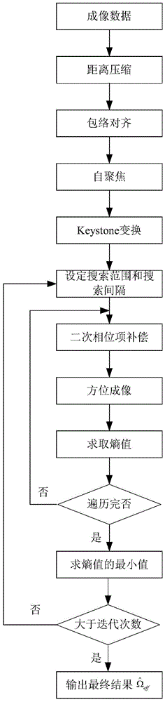
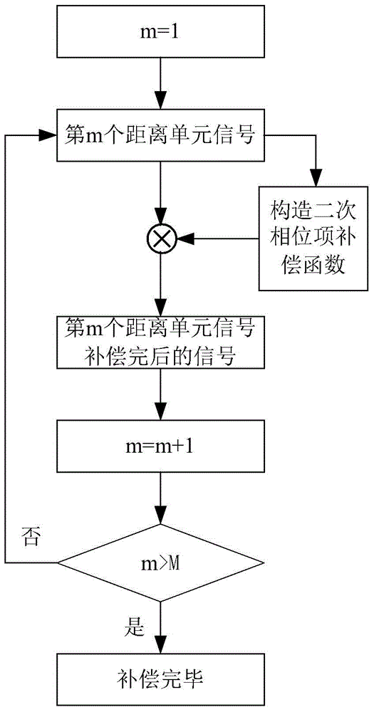
[0029] The method for estimating the effective rotation speed based on the principle of minimum entropy is first to perform distance compression and translation compensation (envelope alignment and self-focusing) on ​​the imaging data, and secondly to perform Keystone transformation on the signal after self-focusing to correct the linear distance walk, and then determine The median value of the effective rotation speed, the search interval and the number of search points, and then use each effective rotation speed to be estimated to perform secondary phase item compensation on the Keystone transformed signal, and then perform azimuth imaging and...


PUM


Abstract

The invention provides a retrosynthetic aperture radar azimuth calibration method which comprises the steps of carrying out range compression and translation compensation on imaging data, carrying out Keystone transformation correction linear range walking on a self-focused signal, determining medians of effective rotational speeds, a search interval and search point number, carrying out secondary phase term compensation on a signal after keystone transformation with each effective rotational speed to be estimated, carrying out azimuth imaging and obtaining an image entropy, after traversing all the effective rotational speeds to be estimated, searching the minimum image entropy, and taking the effective rotational speed corresponding to the minimum image entropy as the estimated effective rotational speed. After obtaining the estimated effective rotational speed, the search is carried out in a smaller interval near the value, the whole process is iterated for 3-4 times, and very high estimated accuracy can be achieved.

Description

technical field [0001] The invention relates to the field of radar imaging, in particular to an inverse synthetic aperture radar azimuth calibration method. Background technique [0002] Inverse Synthetic Aperture Radar (ISAR), as an all-day and all-weather long-range high-resolution sensor, has important application value in moving target imaging and target recognition. In automatic target recognition systems based on ISAR imaging, it is preferable to obtain the scale of the target. The scale factor in the distance direction is given by , where c is the speed of light and B is the bandwidth of the signal. The azimuth scale factor is given by determined, where λ is the wavelength of the transmitted signal, and Ω eff is the effective rotational speed, and T is the imaging accumulation time. [0003] In general, Ω eff If it is not known in advance, then the angle at which the object will turn during imaging is also not available. So far, there are about 4 types of ISA...

Claims


Application Information

Patent Timeline
Patent Type & Authority Patents(China)
IPC IPC(8): G01S7/40G01S13/90
CPCG01S13/904G01S13/9064
Inventor 苏军海
Owner NO 20 RES INST OF CHINA ELECTRONICS TECH GRP
Why Eureka
Try Eureka