A fuse installation structure

An installation structure and fuse technology, applied in the field of electrical components, can solve the problems of accidental contact conduction, danger, easy to fall off, etc., and achieve the effects of enhanced reliability, accurate and reliable positioning, and reliable fixing

Active Publication Date: 2017-01-18
ANHUI JIANGHUAI AUTOMOBILE GRP CORP LTD
View PDF1 Cites 0 Cited by
  • Summary
  • Abstract
  • Description
  • Claims
  • Application Information

AI Technical Summary

Problems solved by technology

However, in actual operation, first of all, since the fuse is always in the fuse box, the operator cannot visually confirm whether the fuse has indeed broken away from the contact with the metal terminal. Contact, in the follow-up maintenance work, the operator is actually operating with electricity, this kind of misoperation is very dangerous, and after installation, it can only be visually judged whether the assembly is in place, but it cannot be accurately judged; secondly , even if the operator does pull out the fuse so that it is out of contact with the metal terminal, it is very important to maintain a continuous and reliable power-off state when the fuse is pulled out. When the operator accidentally presses down on the fuse with his body or tools, The fuse will return to the installed state and contact the metal terminal. At this time, the operator does not realize that the fuse has returned and the circuit is connected. The disconnection assurance measures between the terminal and the pin of the fuse lack effective isolation protection, maintenance, operation errors, etc., which may easily lead to accidental contact conduction
In addition, prior art 2 still cannot solve the problem of inconvenient disassembly and assembly of the fuse and easy falling off
Moreover, the second prior art still needs to use a special coupler (i.e., a safety clip-type removal tool) to remove the insurance, and put it into the installation transition structure designed in the fuse box.

Method used


Image

  • A fuse installation structure
  • A fuse installation structure
  • A fuse installation structure

Examples


Embodiment Construction

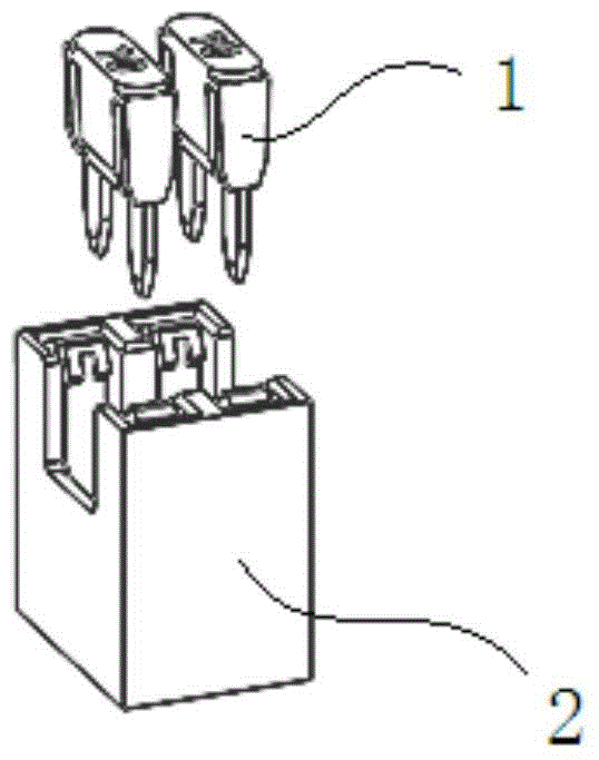
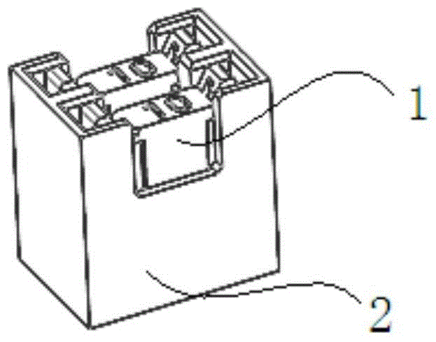
[0054] refer to Figure 6 , the fuse installation structure in this embodiment includes two parts, the fuse seat 200 and the electrical box body 300, and for clarity, the metal terminal 400 fixed in the electrical box body 300 is exploded as a single component. The fuse seat 200 is used to install the fuse 100 , and the fuse seat 200 is inserted into the electrical box body 300 to complete the installation of the fuse 100 .

[0055] refer to Figure 7 , in this embodiment, the fuse 100 is a 10A blade type fuse, the fuse 100 has two pins 110, and the length of the pins is h7. This fuse is commonly used in the automotive field. The blade fuse 100 is used as an example in the following descriptions, but those skilled in the art should understand that the fuse holder 200 can also be installed with various types and types of fuses such as glass tube type and ceramic tube type.

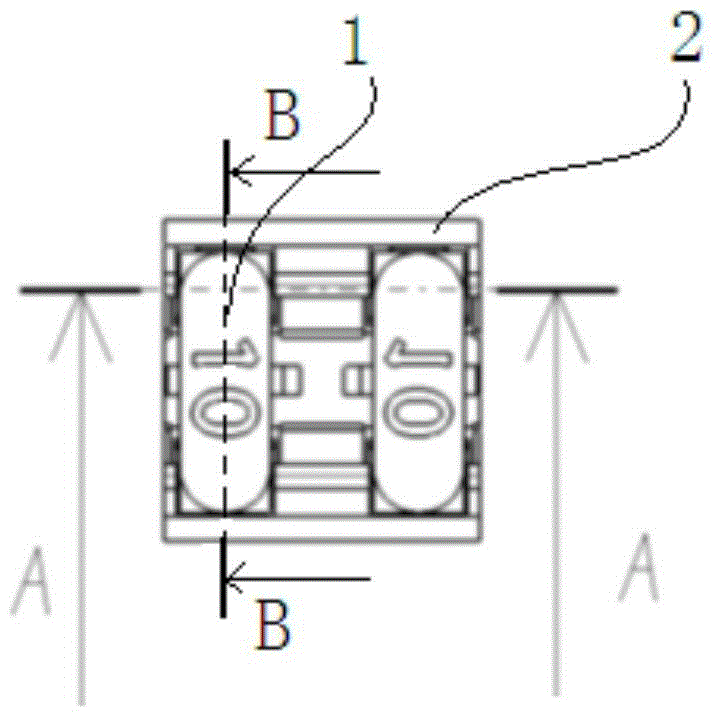
[0056] combine Figure 8 , Figure 9 with Figure 16 , Figure 25 , the fuse seat 200 has a fuse ...


PUM


Abstract

The invention provides a fuse mounting structure. The fuse mounting structure comprises an electric appliance box main body and a fuse holder, wherein slots are formed in the two sides of the electric appliance box main body; first bosses and second bosses are arranged inside the slots; the fuse holder comprises a fuse mounting part, clamping parts positioned on the two sides of the fuse mounting part, and two insertion parts positioned below the fuse mounting part; the insertion parts comprise sliding chutes with sealed upper ends and lower ends, and bulges protruded in the directions far away from the sliding chutes; the insertion parts of the fuse holder are inserted in the slots of the electric appliance box main body; the second bosses are positioned in the sliding chute; under the working condition, the first bosses are buckled with the bulges, and meanwhile the second bulges are not in contact with the lower ends of the sliding chutes; under the out-of-service condition, the first bosses squeeze the bulges to enable the insertion parts to be deformed towards the sliding chutes, and meanwhile the second bosses are in contact with the lower ends of the sliding chutes. The fuse mounting structure disclosed by the invention is convenient to operate and high in safety.

Description

technical field [0001] The invention relates to the field of electrical components, in particular to a fuse installation structure. Background technique [0002] Fuse (also known as fuse) is an important protection device to prevent current overload. [0003] The fuse installation structure in prior art one is as follows: Figure 1 to Figure 5 As shown, the fuse 1 is directly inserted into the electrical box body 2, and the metal terminal 3 in the electrical box body 2 clamps the fuse 1. The entire installation structure consists of figure 1 The detached state shown is entered as figure 2 The installation status shown. [0004] The fuse mounting structure in the prior art has only such figure 1 The separation state where the shown fuse 1 is completely separated from the electrical box body 2 and as shown figure 2 The shown fuse 1 and the electrical box body 2 are installed in two states, and rapid switching between the two states cannot be realized. When it is neces...

Claims


Application Information

Patent Timeline
Patent Type & Authority Patents(China)
IPC IPC(8): H01H85/22
CPCH01H85/22
Inventor 孙丰超汪振兴孟胥里李荫荣王春芝王政
Owner ANHUI JIANGHUAI AUTOMOBILE GRP CORP LTD
Why Eureka
Try Eureka