Lateral insertion spinal implant

An implant and spine technology, applied in the direction of spinal implants, joint implants, joint implants, etc., can solve problems such as lack of spinal strength and limited success of spinal fusion

Active Publication Date: 2015-03-04
DEPUY SYNTHES PROD INC
View PDF10 Cites 1 Cited by
  • Summary
  • Abstract
  • Description
  • Claims
  • Application Information

AI Technical Summary

Problems solved by technology

However, the success of spinal fusion is limited due to several factors
For example, a spacer or implant or cage used to fill the space left by a removed disc may not be strong enough to support the spine

Method used


Image

  • Lateral insertion spinal implant
  • Lateral insertion spinal implant
  • Lateral insertion spinal implant

Examples


Embodiment Construction

[0031] Specific implementations of the present disclosure will now be described more fully hereinafter. Indeed, these implementations may be embodied in many different forms and should not be construed as limited to the implementations set forth herein; rather, these implementations are provided so that this disclosure will satisfy applicable legal requirements. As used in this specification and in the appended claims, the singular forms "a," "an," and "the" include plural referents unless the context clearly dictates otherwise. As used herein, the term "comprises" and variations thereof are used synonymously with the term "comprises" and variations thereof, and are open-ended, non-limiting terms.

[0032] In performing extensive back surgery, surgeons are often required to utilize pedicle screws and rods. These pedicle screws and rods are components of a rigid stabilization system that tend to intrude into the surrounding tissue and vasculature. The present disclosure is le...


PUM


Abstract

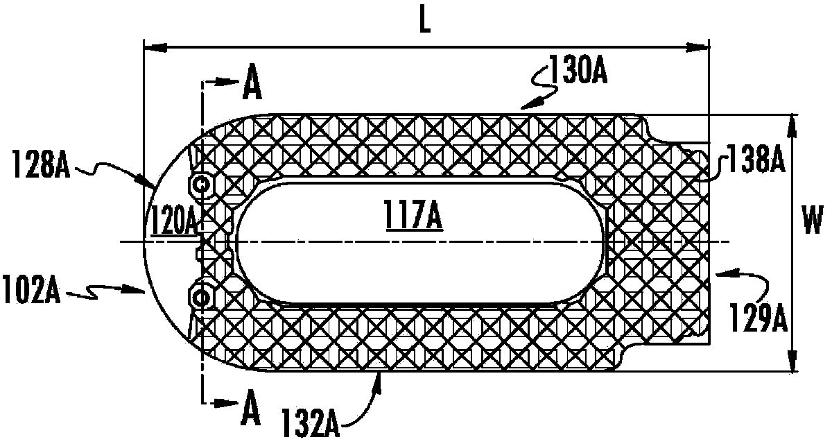
The present disclosure relates to a spinal implant. The spinal implant may be used for lateral insertion into an intervertebral disc space. For example, the spinal implant may include a spacer body to which a plate is fixed. The intervertebral spacer body may include a pair of opposite sides having a pyramid-shaped teeth to fuse to bone. The plate defines at least one upper and lower borehole that each receives a screw. Each screw attaches the plate to a vertebral body between which the intervertebral spacer body is inserted. The boreholes may include locking threads that are adapted to lock the screws into place by engaging complementary locking threads of head of the screw.

Description

Background technique [0001] Spondylolisthesis is the term used to describe the forward sliding of one vertebra over the vertebrae below it. This often occurs due to the presence of spondylolisthesis in the upper vertebrae. There are two main parts of the spine that keep the vertebrae aligned, and they include the intervertebral discs and the facet joints. When spondylolisthesis occurs, the face joints can no longer pull on the vertebrae. The discs can slowly elongate under increased pressure and allow the upper vertebrae to slide forward. In most cases, the elongation of the disc allows only a small amount of forward sliding. [0002] Surgical treatment of spondylolisthesis requires addressing both mechanical and compressive symptoms, if present. The purpose of surgery is to remove pressure on the spinal nerves (ie decompression) and to provide stability to the thoracic / lumbar spine. In most cases of spondylolisthesis, decompression should be accompanied by joining one ve...

Claims


Application Information

Patent Timeline
Patent Type & Authority Applications(China)
IPC IPC(8): A61F2/44A61F2/46A61F2/30A61B17/86
CPCA61F2/4465A61F2002/30576A61F2002/30843A61B17/8615A61F2002/3008A61F2002/30504A61B17/863A61F2002/305A61B17/864A61F2/447A61F2310/00131A61F2/4611A61F2002/30787A61F2002/30578A61F2002/30607A61F2310/00023A61F2310/00095A61F2002/30616A61F2002/4475A61F2002/30785A61F2002/30593
Inventor L.劳伦塞S.赛德哈M.怀特B.R.佩里K.M.斯德迪奎
Owner DEPUY SYNTHES PROD INC
Why Eureka
Try Eureka