Mechanical seal

A technology of mechanical seal and sealing cover, which is applied in the direction of engine sealing, mechanical equipment, engine components, etc., and can solve the problems of weight increase and space limitation

Inactive Publication Date: 2015-03-04
EAGLE INDS +1
View PDF5 Cites 2 Cited by
  • Summary
  • Abstract
  • Description
  • Claims
  • Application Information

AI Technical Summary

Problems solved by technology

Enlarging the body thickness (axial thickness) of the seal cover 90 in order to ensure sufficient strength results in an increase in weight proportional to the body thickness and space limitations in the fixing position of the mechanical seal.

Method used


Image

  • Mechanical seal
  • Mechanical seal
  • Mechanical seal

Examples


Embodiment 1

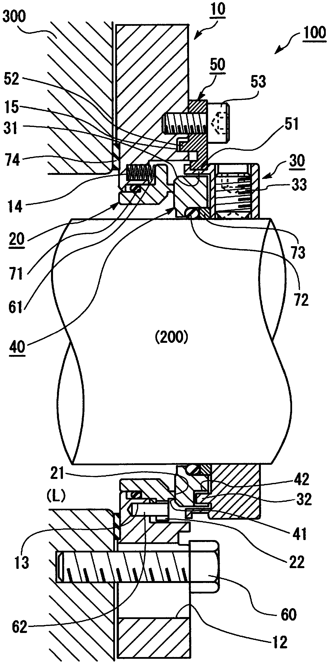
[0036] Refer below Figure 1 ~ Figure 2 A mechanical seal according to Embodiment 1 of the present invention will be described. In this embodiment, a mechanical seal commonly known as a cartridge mechanical seal is taken as an example, which simplifies the assembly work by providing a set plate temporarily fixing the seal cover and the collar of the rotating shaft.

[0037]

[0038] special reference figure 1 The overall structure of the mechanical seal in Embodiment 1 of the present invention will be described. figure 1 A schematic cross-sectional view showing a mechanical seal according to Embodiment 1 of the present invention in which a rotating shaft and a housing are assembled. figure 1 In , the cross-section of the mechanical seal is a cross-section including the central axis of each annular member constituting the mechanical seal (coinciding with the central axis of the rotating shaft). However, for the convenience of explanation, the phase of the cross-section i...

Embodiment 2

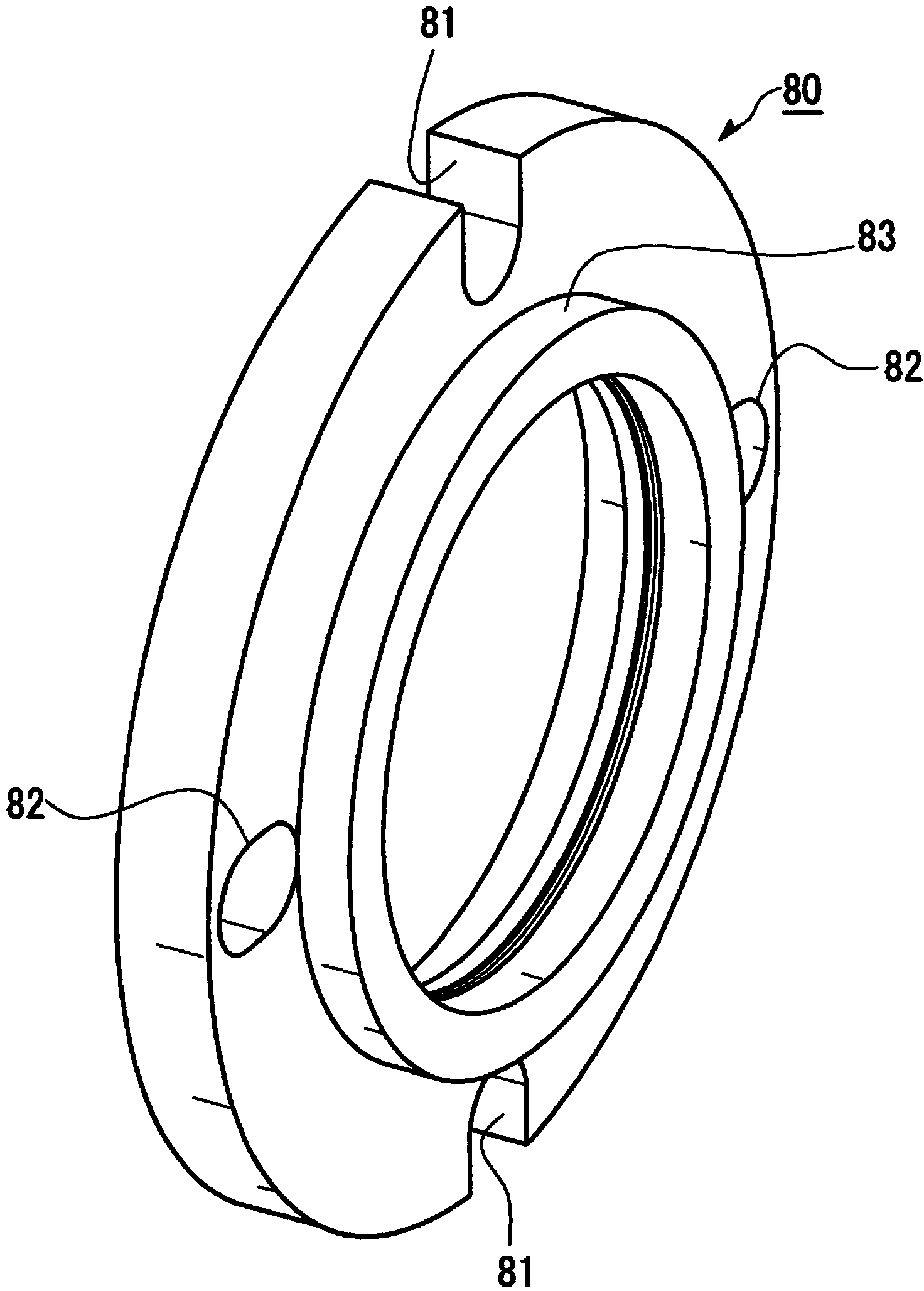
[0051] image 3 The sealing cover of the mechanical seal of Example 2 of the present invention is shown. image 3 It is a perspective view seen from the collar side when the mechanical seal of Example 2 is assembled. Such as image 3 As shown, the sealing cover 80 includes two U-shaped slots 81 and two elongated holes 82 for bolt fastening that are arranged alternately and at equal intervals in the circumferential direction of the shaft hole. The long hole 82 is elongated in the radial direction of the shaft hole, and is provided such that the innermost position of the hole through which the bolt shaft can pass is closer to the inner side than the innermost position of the U-shaped groove 81 through which the bolt shaft portion can pass. Since the effect achieved by the sealing cap 80 configured in this way is the same as that of the sealing cap 10 of Embodiment 1, description thereof will be omitted. The sealing cover 80 includes an annular protrusion 83 provided inside th...


PUM


Abstract

Provided is a mechanical seal equipped with a seal cover which is highly versatile and which is, even if affixed to a housing by two bolts, less likely to deform. A mechanical seal (100) is provided with a rotating ring (40), a stationary ring (20), and a seal cover (10) which mounts the stationary ring (20) to a housing (300). The mechanical seal is characterized in that the seal cover (10) has two U-shaped grooves (11) and two long holes (12), the U-shaped grooves (11) and the long holes (12) being used to fasten bolts and being arranged alternately at equal intervals in the circumferential direction of a shaft hole, in that the long holes (12) are long in the radial direction of the shaft hole, and in that the innermost positions of the long holes (12), the innermost positions being those through which the shanks of the bolts can be inserted, are located on the inner side of the innermost positions of the U-shaped grooves (11), the innermost positions being those through which the shanks of the bolts can be inserted.

Description

technical field [0001] The invention relates to a mechanical seal for sealing an annular gap between a housing and a rotating shaft. Background technique [0002] In the mechanical seal of general-purpose industrial pumps (general-purpose pumps), the sealing surface is formed between a stationary ring and a rotating ring, wherein the stationary ring is provided on the side of the seal cover fixed to the casing (stuffing box) of the pump body, The rotating ring is arranged on one side of a collar fixed on the rotating shaft. The sealing cover is usually bolted to the end face of the housing via a gasket. On the end face of the shell, two or four fastening points (bolt holes or stud bolts) are usually arranged at equal intervals in the circumferential direction of the shaft hole, but even if the diameter of the rotating shaft is the same, the fastening positions of these fastening points ( The radial position relative to the center of the shaft hole) may also vary from pump ...

Claims


Application Information

Patent Timeline
Patent Type & Authority Applications(China)
IPC IPC(8): F16J15/34
CPCF16J15/3468F16J15/3464F16J15/3472F16J15/348F16J15/166
Inventor 柳泽隆佐藤贵德
Owner EAGLE INDS
Why Eureka
Try Eureka