Check patentability & draft patents in minutes with Patsnap Eureka AI!

Electrowetting display device

An electrowetting display and equipment technology, applied in optical components, instruments, optics, etc., can solve the problem of increasing power and achieve the effect of reducing voltage

Active Publication Date: 2017-06-09
LIQUAVISTA BV
View PDF3 Cites 0 Cited by
  • Summary
  • Abstract
  • Description
  • Claims
  • Application Information

AI Technical Summary

Problems solved by technology

This increases the power required to cause the desired display effect

Method used


Image

  • Electrowetting display device
  • Electrowetting display device
  • Electrowetting display device

Examples


Embodiment Construction

[0018] The present invention relates to electrowetting devices, in particular, the present invention relates to electrowetting display devices.

[0019] Before describing the detailed embodiments with reference to the drawings, the descriptions thereof will be used to describe the embodiments in an overview form.

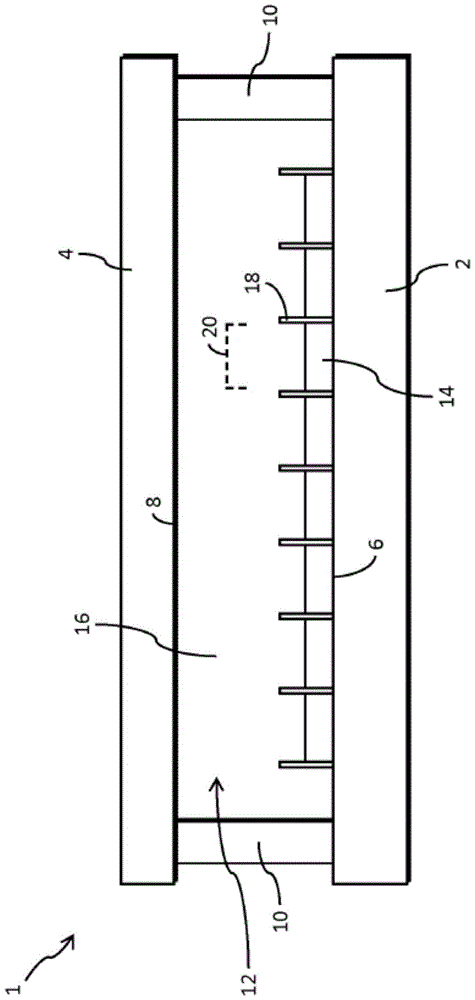
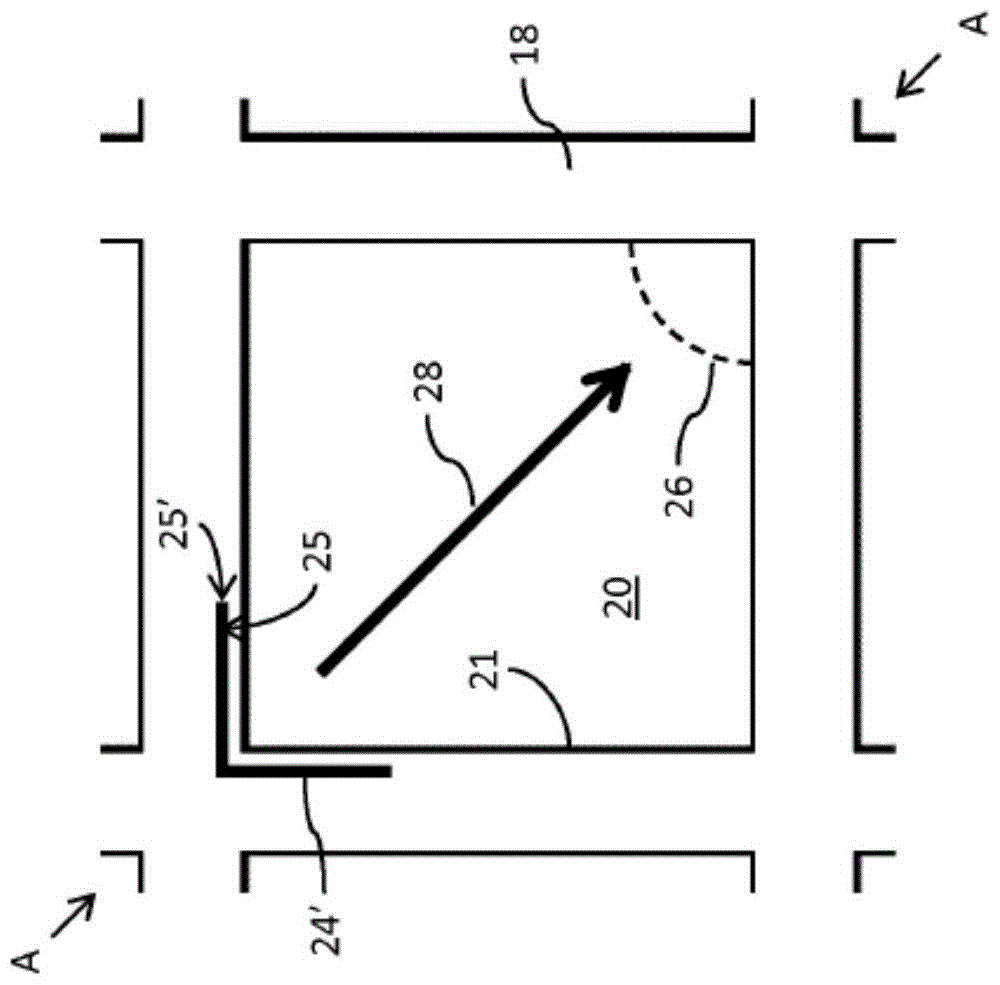
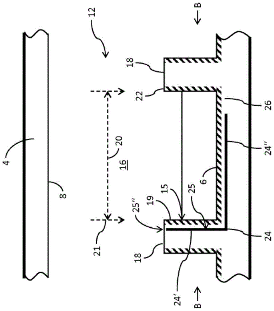
[0020] According to an embodiment, there is provided an electrowetting display device comprising a picture element comprising: a first support plate and a second support plate; a space between the first support plate and the second support plate, The space includes a first fluid and a second fluid immiscible with the first fluid; wherein the first support plate includes: a display area adjacent to the space, the first fluid is confined within the display area, the display area has a second A surface, the first surface adjoining the space; a wall protruding from the first support plate and formed outside the display area along at least a part of the periphery of the ...


PUM


Abstract

An electrowetting display device comprises a picture element having a first support plate and a second support plate having a space therebetween having a first fluid and a second fluid immiscible with the first fluid. The first support plate comprises a display area, adjoining the space, within which the first fluid is confined and having a first surface adjoining the space. A wall protrudes from the first support plate and is formed outside the display area along a part of the perimeter of the display area. The wall has a second surface facing the display area and adjoining the space. An electrode has a first portion adjacent to the first surface and a second portion adjacent to at least a part of the second surface such that a surface of the second portion including a long side of a cross section of the second portion faces the display area.

Description

technical field [0001] The invention relates to an electrowetting display device comprising a picture element. Background technique [0002] Electrowetting display devices comprising two support plates are known. One of these support plates comprises a pattern of walls defining picture elements of the display device. The area between the walls of the picture elements is called the display area, on which the display effect occurs. [0003] The space between the support plates contains a first fluid and a second fluid that are immiscible with each other. The configuration of the walls confines the first fluid within the display area. Electrodes are provided in the support plate within the display area. The first fluid causes a layer to form on the display area when no voltage is provided between the electrodes and the second fluid. Application of the voltage changes the configuration of the first fluid and the second fluid to provide a display effect. [0004] A problem ...

Claims


Application Information

Patent Timeline
IPC IPC(8): G02B26/00
CPCG02B26/005
Inventor 帕维尔·诺沃泽洛夫酒井亨丹尼尔·菲古拉安德里亚·吉拉尔杜
Owner LIQUAVISTA BV
Features
  • R&D
  • Intellectual Property
  • Life Sciences
  • Materials
  • Tech Scout
  • Unparalleled Data Quality
  • Higher Quality Content
  • 60% Fewer Hallucinations
Learn More