Check patentability & draft patents in minutes with Patsnap Eureka AI!

Multi-cell rotary end effector mechanism

A technology of end effectors and rotary actuators, which is applied in semiconductor/solid-state device manufacturing, manipulators, electrical components, etc., and can solve the problems of manufacturing output, battery efficiency sacrifice, etc.

Inactive Publication Date: 2015-03-04
VARIAN SEMICON EQUIP ASSOC INC
View PDF3 Cites 0 Cited by
  • Summary
  • Abstract
  • Description
  • Claims
  • Application Information

AI Technical Summary

Problems solved by technology

However, manufacturing output cannot be sacrificed to increase cell efficiency

Method used


Image

  • Multi-cell rotary end effector mechanism
  • Multi-cell rotary end effector mechanism
  • Multi-cell rotary end effector mechanism

Examples


Embodiment Construction

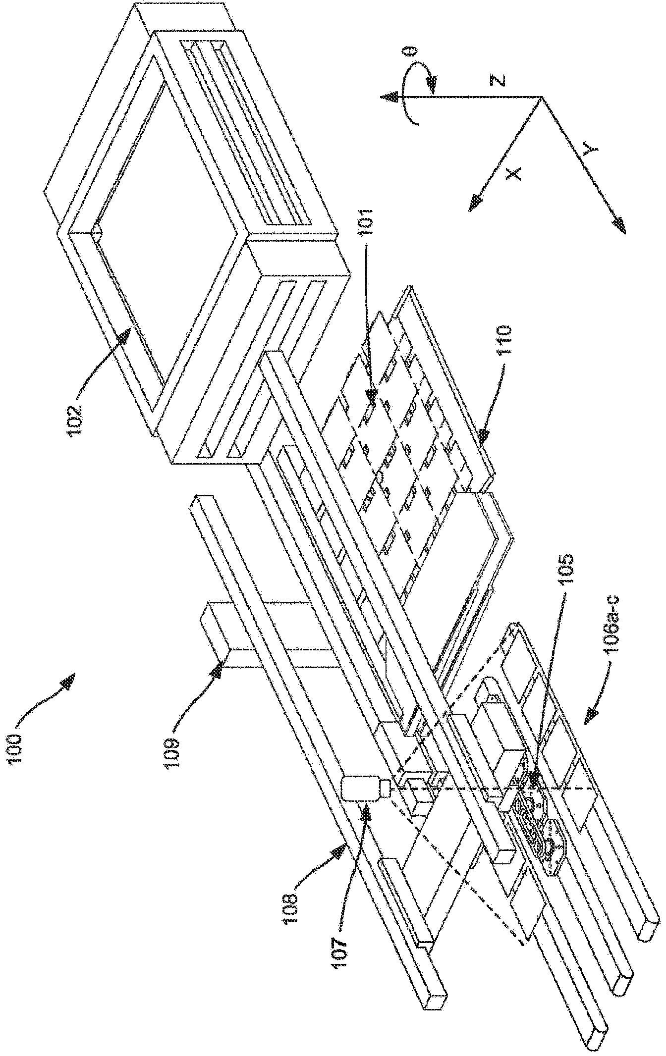
[0018] A workpiece handling system for solar cells is described here. However, embodiments may be used with other workpieces, such as semiconductor wafers, light emitting diodes (LEDs), and silicon-on-insulator (SOI) wafers, or other components. In addition to being used with ion implantation equipment, the workpiece handling system can also be used with other processing equipment, such as deposition, etching or other workpiece processing systems. Therefore, the present invention is not limited to the specific examples described below.

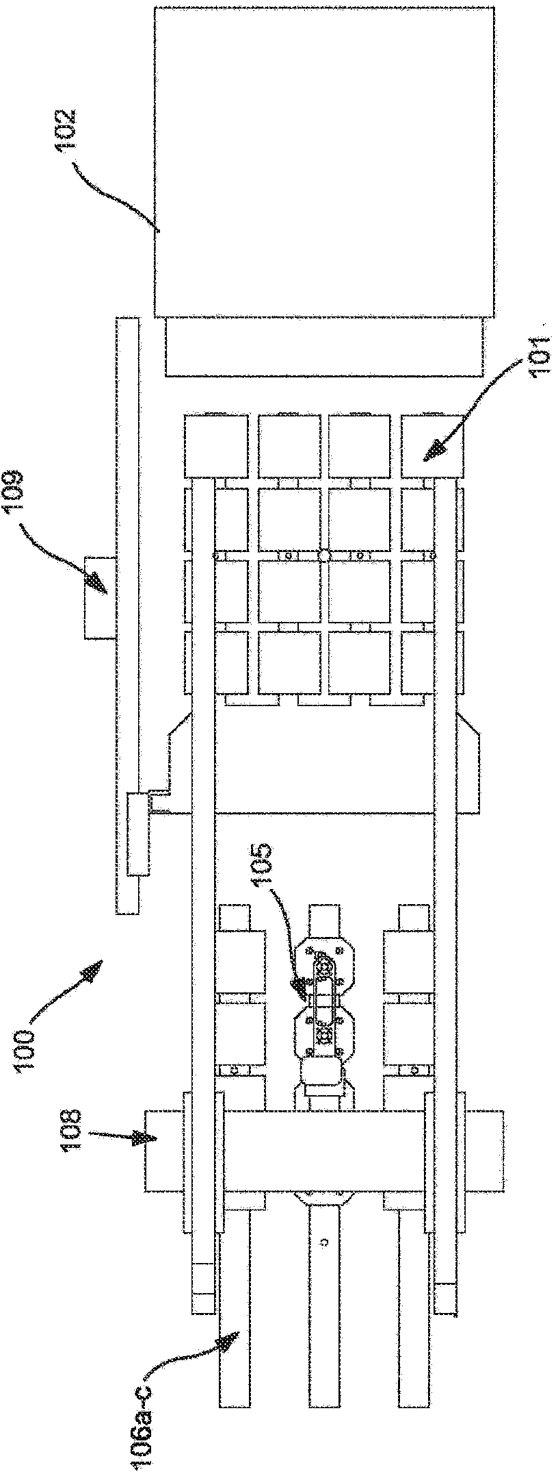
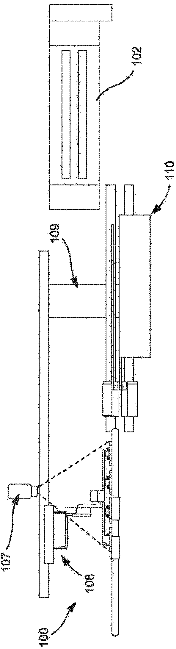
[0019] Figure 1 to Figure 3 The illustrated example workpiece handling system 100 can process over 2000 wafers per hour (wph) using a 4x4 workpiece matrix. Of course, other workpiece matrix designs can also be used, and the embodiment here is not limited to only 4x4 matrix. These figures represent a workpiece handling system, each individual element of which will be described in more detail below. figure 1 A perspective view showing the b...


PUM


Abstract

A rotary end effector for use for the high speed handling of workpieces, such as solar cells, is disclosed. The rotary end effector is capable of infinite rotation. The rotary end effector has a gripper bracket, capable of supporting a plurality of grippers, arranged in any configuration, such as a 4×1 linear array. Each gripper is in communication with a suction system, wherein, in some embodiments, each gripper can be selectively enabled and disabled. Provisions are also made to allow electrical components, such as proximity sensors, to be mounted on the rotating gripper bracket. In another embodiment, an end effector with multiple surfaces, each with a plurality of grippers, is used.

Description

technical field [0001] The present invention relates to workpiece manipulation, and more particularly to a multi-unit rotary end effector mechanism. Background technique [0002] Ion implantation is a standard technique for introducing impurities that can change conductivity to a workpiece. The desired impurity material is ionized in the ion source, the ions are accelerated to form an ion beam of predetermined energy, and the ion beam is directed at the workpiece s surface. The energetic ions in the ion beam penetrate into the bulk of the workpiece material and become embedded in the crystal lattice of the workpiece material and form a region of desired conductivity. [0003] Ion implantation has proven to be a viable method for doping solar cells. Two things of greatest concern to the solar cell manufacturing industry are manufacturing output and cell efficiency, which measures how much energy is converted into electricity. To remain competitive in solar cell manufacturi...

Claims


Application Information

Patent Timeline
IPC IPC(8): H01L21/677H01L21/683
CPCB25J15/0616H01L21/6838H01L21/67754B25J19/0041B25J9/10B25J19/0029H01L21/67736H01L21/67712
Inventor 杰森·夏勒罗伯特·B·宝佩特
Owner VARIAN SEMICON EQUIP ASSOC INC
Features
  • R&D
  • Intellectual Property
  • Life Sciences
  • Materials
  • Tech Scout
  • Unparalleled Data Quality
  • Higher Quality Content
  • 60% Fewer Hallucinations
Learn More