A special mold for manufacturing grinding wheel

A grinding wheel and mold technology, which is applied in the field of special molds for manufacturing grinding wheels, can solve problems affecting the quality of grinding wheels and reduce the service life of molds, and achieve the effects of reducing production costs, prolonging service life, and reducing friction

Active Publication Date: 2017-01-11
甘虹
View PDF6 Cites 0 Cited by
  • Summary
  • Abstract
  • Description
  • Claims
  • Application Information

AI Technical Summary

Problems solved by technology

During the pressing process, the mold bears a large pressure, and at the same time, the relative motion between the outer mold and the inner upper mold is relatively long, resulting in a large friction force. The friction consumption caused by friction will affect the quality of the grinding wheel on the one hand, and reduce it on the other hand. The service life of the mold

Method used


Image

  • A special mold for manufacturing grinding wheel
  • A special mold for manufacturing grinding wheel
  • A special mold for manufacturing grinding wheel

Examples


Embodiment 1

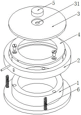
[0059] A kind of special mold for manufacturing grinding wheel of the present embodiment, such as figure 1 , figure 2 , image 3 As shown, it is mainly realized through the following technical solutions: a special mold for manufacturing grinding wheels, including a bottom mold 1, an outer upper mold 2, an inner upper mold 3, an inner middle mold 4, a core mold 5 and an elastic connector 6, the core The mold 5 is set inside the core hole 31 set in the center of the top surface of the inner upper mold 3, and the inner upper mold 3, the inner middle mold 4 and the bottom mold 1 are arranged coaxially from top to bottom and are all set inside the outer upper mold 2, The outer upper mold 2 is connected to the bottom mold 1 through an elastic connector 6; the bottom mold 1 includes a fixedly connected support cylinder 11 and a lower mounting platform 12, the center of the support cylinder 11 is provided with a first demoulding channel 13, and the inner middle mold 4 It is fixed o...

Embodiment 2

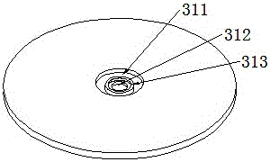
[0067] This embodiment is further optimized on the basis of the above embodiments, such as image 3 As shown, further, the core hole 31 is a through hole, including an upper through hole 311 and a lower through hole 312 arranged coaxially; the aperture of the upper through hole 311 is equal to the aperture of the core mold 5 and is larger than the lower through hole 312 The bottom surface of the upper through hole 311 is provided with a buffer pad 313, and the bottom surface of the mandrel 5 is close to the top surface of the buffer pad 313. Other parts of this embodiment are the same as those of the foregoing embodiments, so details are not repeated here.

Embodiment 3

[0069] This embodiment is further optimized on the basis of the above embodiments, such as Figure 4 As shown, further, the core hole 31 is an equal-diameter through hole and the aperture of the core hole 31 is equal to the outer diameter of the core mold 5; a connecting plate 46 is arranged in the middle of the second demoulding channel 43, and the core mold 5 is fixed In the center of the connection plate 46 . Other parts of this embodiment are the same as those of the foregoing embodiments, so details are not repeated here.


PUM


Abstract

The invention discloses a special die for manufacturing a grinding wheel. The special die for manufacturing the grinding wheel comprises a bottom die, an outer upper die, an inner upper die, an inner middle die, a core die and an elastic connecting piece, the core die is sleeved in the core hole in the top of the inner upper die, the inner upper die, inner middle die and bottom die are coaxially arranged in sequence from the top to bottom and sleeved in the outer upper die, and the outer upper die is connected with the bottom die through the elastic connecting piece; the inner middle die is firmly connected with a bottom die support barrel, and the outer diameter of the inner middle die is larger than that of the support barrel; the outer upper die is sleeved with the bottom die through an annular clamp at the bottom, and the outer upper die is in limit connection with the inner middle die; a cavity for forming the grinding wheel is arranged among the inner wall of the outer upper die higher than the top surface of the inner upper die, the outer wall of the core die higher than the top surface of the inner upper die and the top surface of the inner upper die. The special die for manufacturing the grinding wheel is capable of reducing the friction consumption of the die, guaranteeing the grinding wheel production quality and prolonging the service life of the die.

Description

technical field [0001] The invention relates to the field of grinding wheel manufacturing, in particular to a special mold for manufacturing grinding wheels. Background technique [0002] As we all know, a grinding wheel is a tool for cutting or grinding, and a grinding wheel mold is a device for manufacturing grinding wheels. The existing grinding wheel mold mainly includes an outer mold, an inner upper mold and a mold core. A cavity is formed between the inner wall of the outer mold and the plane of the inner upper mold and sand grains are set. The grinding wheel is formed by applying pressure to the mold through a high pressure head, and finally it is demoulded. Get a grinding wheel. During the pressing process, the mold bears a large pressure, and at the same time, the relative motion between the outer mold and the inner upper mold is relatively long, resulting in a large friction force. The friction consumption caused by friction will affect the quality of the grinding...

Claims


Application Information

Patent Timeline
Patent Type & Authority Patents(China)
IPC IPC(8): B24D18/00
CPCB24D18/0009
Inventor 甘虹
Owner 甘虹
Why Eureka
Try Eureka